Injection molding multi-component joint demoulding mechanism
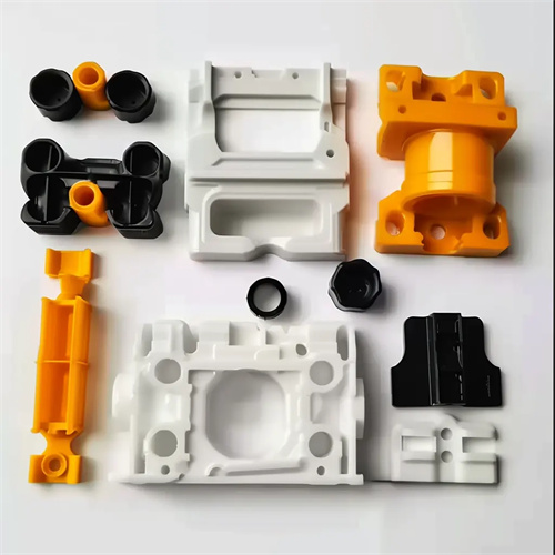
The multi-component, combined ejection mechanism for injection molding is a complex ejection system designed for complex, large, or undercut plastic parts. It typically combines multiple ejection components, including ejector pins, ejector plates, lifters, and core pullers. Key requirements include coordinated operation and uniform force distribution among these components to prevent deformation or damage during the ejection process. For example, for automotive plastic parts with internal bosses and external ribs, the combined ejection mechanism must simultaneously activate the lifter (which releases the internal boss), the ejector pin (which releases the main body), and the ejector plate (which releases the bottom). The sequence of these components’ movements must be strictly controlled, with the lifter first extracting the internal boss, followed by the ejector pin and ejector plate, ensuring smooth part release from the mold cavity. The coordinated operation of this combined mechanism is ensured by mold guides and limiters. For example, a linkage lever is placed between the lifter and ejector plate to ensure the ejector plate activates only after the lifter core pulls into position, with the time difference between these two mechanisms kept within 0.5-1 second.
The power transmission of a multi-component ejection mechanism for injection molding requires reliable and stable performance. The injection molding machine’s ejector cylinder is typically the primary power source, with power distributed to the various ejection components via push rods, tie rods, and other components. For large or complex plastic parts, hydraulic or pneumatic auxiliary power can be added to improve ejection force and motion precision. For example, when producing large plastic housings weighing over 5kg, the ejection mechanism utilizes a “main ejector cylinder + two hydraulic cylinders” power system. The main ejector cylinder drives the central ejector plate, while the two hydraulic cylinders drive the side ejector pins. Proportional valves control the pressure and speed of the hydraulic cylinders to ensure even distribution of ejection force between the ejector plate and ejector pins (with an ejection force deviation of no more than 5%), thus preventing warping of the plastic part due to uneven force. The strength of power transmission components (such as push rods and pull rods) needs to be checked. 45# steel is used after quenching and tempering (hardness HB220-250). The diameter is determined based on the demoulding force. For example, when the total demoulding force is 50kN, the push rod diameter is 20mm, and the number is not less than 4, symmetrically distributed to ensure balanced force transmission.
The stroke control of the multi-component ejector mechanism for injection molding requires precise control. The ejection distance of each ejector component must be determined based on the part structure to ensure that the part is completely released from the mold cavity and does not interfere with other mold components. The ejector pin’s ejection distance is typically 2-5mm greater than the part’s height. For example, for a 30mm tall part, the ejector pin’s ejection distance should be 33mm to ensure that the part is completely clear of the mold cavity surface. The core pull distance of the inclined ejector should be 1-2mm greater than the undercut depth. For example, if the inner boss undercut depth is 5mm, the core pull distance of the inclined ejector should be 6mm to prevent the part from being caught in the undercut during ejection. The stroke of each component in the combined mechanism should be controlled by a limit block or travel switch. For example, the maximum ejection distance of the ejector plate is limited by a limit pin fixed to the movable platen. The clearance between the limit pin and the ejector plate is the set ejection distance, with an error control range of ±0.1mm. For molds used in automated production, position sensors can be installed on the ejector mechanism to monitor the stroke position of each component in real time. Immediately signal any deviation from the stroke to prevent mold damage or part rejection.
The guiding and lubrication design of the multi-component ejection mechanism in injection molding is critical to ensuring long-term stable operation. All moving parts must be equipped with high-precision guides. Guide pins and sleeves are placed between the ejector plate and the movable platen. The diameter of the guide pins is determined by the size of the ejector plate, ranging from 16-20mm for small and medium-sized molds and 25-30mm for large molds. The clearance should be controlled within 0.02-0.05mm to ensure smooth, undeflected movement of the ejector plate. A guide groove should be provided between the lifter and the slider, with a clearance of 0.03-0.06mm. Wear-resistant materials (such as bronze inserts) should be used to reduce wear during movement. Lubrication points in the ejector mechanism should be regularly greased. The mating surface between the ejector pin and the ejector hole should be lubricated every 1000 molds. Use high-temperature grease (resistant to temperatures ≥150°C) to prevent sticking or wear caused by poor lubrication. For complex moving parts such as the inclined top, a lubricating oil groove can be opened in the slide to store grease to extend the lubrication cycle. For example, a 2mm wide and 1mm deep annular oil groove can be machined at the bottom of the inclined top slide. Replenishing grease every 5,000 molds can meet usage needs.
The design of a multi-component joint ejection mechanism for injection molding must consider the deformation characteristics of the plastic part. For thin-walled, slender, or easily deformable parts, multi-point uniform ejection is required to prevent excessive localized force and warping. For example, the joint ejection mechanism for a large flat plate part (1000mm × 800mm, 2mm wall thickness) features ejectors positioned around the perimeter. Twelve ejectors, each 8mm in diameter and spaced 100mm apart, are evenly spaced in the center of the plate. These ejectors are coordinated with four ejector plates (located at the four corners). During ejection, the ejectors and plates operate synchronously, ensuring uniform force distribution across the part and maintaining a flatness tolerance within 0.5mm/m after demolding. For parts with ribs or bosses, ejection should be positioned away from weak areas. Ejectors should be placed in stronger areas, such as the bosses and ribs. For example, an ejector pin should be placed below the ribs, with its diameter 1-2mm smaller than the rib width. This ensures that ejection force is transmitted through the ribs and avoids ejection marks on the part surface. By rationally arranging the ejection components, the combined demoulding mechanism can minimize deformation of the plastic parts while ensuring smooth demoulding of the plastic parts.