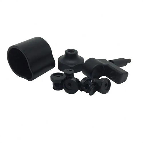
Design of guide pins and sleeves for injection molding movable and fixed templates
The design of guide pins and guide bushings for the movable and fixed injection molding platens is crucial for ensuring mold closing accuracy. Their structural form must be determined based on mold size and precision requirements. Common guide pin types include headed and shouldered guide pins, while guide bushings are categorized as straight or headed. Headed guide pins feature a conical or spherical head , facilitating alignment during mold closing. They are suitable for small and medium-sized molds (platens less than 500mm x 500mm). Guide pins have a diameter of 16-30mm and a length 1.5-2 times the platen thickness. For example, for a 200mm thick platen, the guide pin length should be 300-400mm. Shouldered guide pins, secured to the platen by a shoulder, offer greater positioning accuracy and are suitable for large or high-precision molds. Guide pin diameters range from 30-60mm, with a shoulder diameter 10-20mm larger to enhance fixing strength. For example, a 40mm diameter shouldered guide pin has a 55mm shoulder diameter and uses a transition fit (H7/k6) to connect to the platen bore. The clearance between the guide sleeve and the guide pin must be strictly controlled. For general precision molds, the clearance is 0.02-0.05mm; for high-precision molds (such as optical plastic parts molds), the clearance is controlled at 0.01-0.02mm to ensure that there is no obvious shaking when the mold is closed.
The guide pins and guide bushings of the movable and fixed injection mold plates must be arranged evenly and symmetrically to ensure balanced forces during mold closing and prevent platen deformation. Small and medium-sized molds typically use four guide pins, located at the four corners of the mold plate in a rectangular arrangement. The distance between the center of the guide pin and the edge of the mold plate should be 1.5-2 times the guide pin diameter. For example, a 20mm diameter guide pin should be 30-40mm from the edge. Large molds (with mold plates exceeding 1000mm x 1000mm) require an increased number of guide pins, using 6-8. In addition to the four corner guide pins, additional guide pins should be located in the middle of the long sides to improve guiding stability. For example, for a 1200mm x 800mm mold plate, in addition to the four guide pins at the four corners, one guide pin should be added at 600mm along each of the long sides, for a total of six guide pins. Guide pins must be positioned away from the mold cavity and other components (such as ejector pins and cooling channels). The distance from the mold cavity should be at least twice the guide pin diameter to prevent compromising cavity strength. For example, a 25mm diameter guide pin should be at least 50mm away from the edge of the cavity. For non-rectangular molds, guide pins should be placed symmetrically about the mold’s center of gravity to ensure even distribution of clamping force.
The material selection and heat treatment process for the guide pins and bushings of the movable and fixed injection mold plates directly impact their wear resistance and service life. Guide pins are typically made of 20Cr or SUJ2 (high-carbon chromium bearing steel). Carburized or through-hardened, they achieve a surface hardness of HRC 58-62 and a core hardness of HRC 30-35. This ensures both surface wear resistance and a degree of toughness to prevent impact fracture. Guide bushings are made of bronze (such as ZCuSn10Pb1) or SUJ2. Bronze guide bushings are self-lubricating and suitable for oil-free lubrication applications. SUJ2 guide bushings require grease for improved wear resistance and are suitable for high-speed mold closing (over 0.5 m/s). The guide pin surface is ground to a roughness of Ra ≤ 0.4 μm and a cylindricity tolerance of no more than 0.005 mm/m to ensure a good fit with the guide bushing. The guide bushing’s inner bore roughness is Ra ≤ 0.8 μm, and both ends are rounded (R1-R2) to facilitate guide pin insertion and prevent end wear.
The fit and installation accuracy of the guide pins and guide bushings in the movable and fixed injection molding platens must be strictly controlled to ensure mold closing accuracy. The guide pins and movable platen utilize a transition fit (H7/k6), while the guide bushings and fixed platen utilize an interference fit (H7/r6) or a transition fit (H7/k6). The specific fit depends on mold precision: high-precision molds utilize an interference fit to prevent guide bushing loosening and impacting precision; general molds utilize a transition fit for ease of installation and replacement. The guide pins must be installed with a perpendicularity error of no more than 0.01mm/m, and the guide bushings must be installed with the same perpendicularity error as the guide pins, ensuring coaxiality between the guide pins and bushings within 0.02mm. After installation, a mold closing test is required. The runout of the movable platen during the closing process must be measured with a dial indicator. The maximum runout must not exceed 0.03mm; otherwise, readjustment is required. For complex molds, such as three-plate molds, guide pins and bushings are added to the center plate. Their precision requirements match those of the movable and fixed platens to ensure coordinated movement of the platens.
Lubrication and maintenance of the guide pins and bushings on the movable and fixed injection molding plates are crucial for ensuring long-term, stable mold operation. A maintenance plan should be developed based on mold usage frequency and operating conditions. Lubricate guide pins and bushings every 1,000 molds. Use a high-temperature grease (such as polyurea grease) and apply enough to cover one-third of the guide pin surface. Excessive application can contaminate the molded part. For molds using bronze guide bushings, the lubrication interval can be extended to 3,000 molds, leveraging their self-lubricating properties to reduce maintenance. Regularly inspect guide pins and bushings for wear and measure clearance. Replace the pin or bushing if the clearance exceeds 50% of its initial value. For example, a guide pin or bushing with an initial clearance of 0.03mm should be replaced if the clearance reaches 0.045mm after wear. Scratches or rust on the guide pin surface should be polished with an oilstone before use. Severe damage requires replacement. Through scientific lubrication and maintenance, the service life of the guide pins and sleeves can reach more than 500,000 mold cycles, ensuring the long-term stability of the mold clamping accuracy and reducing the occurrence of defects such as dimensional deviation and flash of plastic parts.