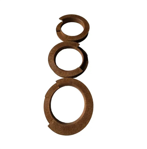
Lateral core pulling mechanism of slider T-block
The lateral core-pulling mechanism of the slider’s T-block is a key device for achieving lateral concave and convex or hole-forming in plastic parts within the mold. Its core structure consists of a T-block, slider, guide groove, and power components (such as inclined guide posts and hydraulic cylinders). The T-block serves as the slider’s guide and support, ensuring a smooth and precise core-pulling process. The horizontal portion of the T-block fits into the T-slot at the slider’s base, while the vertical portion is fixed to the fixed or movable platen, forming a sliding guide. During core pulling, the slider moves along the T-block, achieving lateral core-pulling. The T-block must be made of high-strength and wear-resistant material, typically 40Cr or Cr12MoV. After quenching, its hardness reaches HRC50-55, and its surface roughness Ra is controlled below 0.8μm to reduce friction with the slider. For example, the lateral core pulling mechanism of a certain automotive connector mold uses a T-shaped block made of Cr12MoV material with a hardness of HRC52 after quenching. The clearance with the slider is controlled at 0.03-0.05mm, ensuring that there is no jamming during the core pulling process and the core pulling accuracy reaches ±0.02mm.
The size of the slider’s T-block must be determined based on the core-pulling force and slider size to ensure structural strength and guiding accuracy. The T-block width is typically 1/3-1/2 the slider width. For example, if the slider is 100mm wide, the T-block width should be 40-50mm to ensure sufficient contact area to disperse the core-pulling force. The thickness of the T-block must be determined through strength calculations using the formula: Thickness (mm) = Core-pulling Force (N) × Safety Factor / (Width (mm) × Allowable Material Stress (MPa)). The safety factor is 1.5-2.0, and the allowable stress of 40Cr is 200MPa. For example, for a T-block with a core-pulling force of 50kN and a width of 50mm, the thickness is 50000 × 1.5 / (50 × 200) = 7.5mm. The length of the T-block must be greater than the core-pulling distance of the slider, typically 20-30mm longer. For example, if the core-pulling distance is 80mm, the T-block should be 100-110mm long to ensure sufficient guide length (no less than 1/3 of the T-block length) when the slider is in the maximum core-pulling position. In addition, the mating surface between the T-block and the slider’s T-slot must be ground to a flatness error of no more than 0.01mm/m to ensure a tight fit and prevent the slider from shaking during core-pulling.
The power transmission design for the slider’s T-block lateral core pulling mechanism requires high efficiency and reliability. Common power transmission methods include inclined guide pin drive and hydraulic cylinder drive, respectively suited to different core pulling distances and force requirements. The inclined guide pin drive is suitable for applications with short core pulling distances (typically less than 50mm) and low core pulling forces (less than 30kN). The inclined guide pin mates with guide holes in the slider. During mold closing, the inclined guide pin pushes the slider inward along the T-block (resetting) and during mold opening, it drives the slider outward (core pulling). The inclined guide pin’s inclination angle is typically 15°-25°; excessively large angles can easily cause the slider to self-lock. For example, in the lateral core pulling of small electrical plastic parts (core pulling distance 30mm, force 15kN), an inclined guide pin with a 20° inclination, combined with the T-block guide, ensures smooth core pulling and quick response. Hydraulic cylinder drive is suitable for applications requiring long core pulling distances (50-300mm) and high core pulling forces (30-200kN). The hydraulic cylinder is directly connected to the slide via a piston rod, and the core pulling distance and speed can be precisely controlled by the hydraulic system. For example, lateral core pulling in automobile bumpers (core pulling distance 150mm, force 80kN) is driven by a double-acting hydraulic cylinder, combined with a T-block guide, to achieve core pulling position accuracy within ±0.1mm.
The limiting and locking design of the slider’s T-shaped block in the lateral core-pulling mechanism is crucial for safe operation. Both a core-pulling endpoint limiter and a mold-locking locking device are required to prevent the slider from moving under injection pressure. The core-pulling endpoint limiter typically utilizes a stopper or travel switch. After the slider completes core pulling, the stopper contacts the slider, restricting further movement. The stopper is made of hardened 45# steel (HRC 40-45), with a contact area of at least 50mm² with the slider. For example, for a mechanism with a core-pulling distance of 100mm, a 20mm thick stopper is installed at the slider’s end point to ensure reliable positioning. The mold-locking locking device secures the slider after mold closing to prevent lateral forces during injection from pushing it forward. Common devices include a wedge block and a locking pin. The wedge block’s bevel angle is 2°-3° greater than the guide post (e.g., a 20° guide post and a 22° wedge block), providing a tight fit with the slider’s bevel. The locking force is 1.5-2 times the core-pulling force. For example, for a mechanism with a core pulling force of 50kN, the locking force of the wedge block needs to reach 80-100kN. Through the coordinated action of the T-shaped block and the wedge block, it is ensured that the slider does not loosen during the injection process.
Lubrication and maintenance of the slider’s T-block side core-pulling mechanism are crucial to extending its service life. Regular lubrication and wear inspection are required for the mating surfaces between the T-block and the slider. Lubrication should be performed with high-temperature resistant grease (such as molybdenum disulfide lithium grease) every 1,000 mold cycles to ensure a stable oil film on the mating surfaces and reduce friction and wear. For high-speed core-pulling mechanisms (core-pulling speeds exceeding 300 mm/s), an automatic lubrication system can be installed to automatically relubricate the grease every 500 mold cycles. T-block wear should be measured regularly. If wear exceeds 0.1mm, repair or replacement is necessary. Repair can be performed by overlay welding followed by grinding to restore dimensional accuracy. For example, if a T-block wears 0.15mm wide, overlay welding should be applied to add 0.2mm and then grinding to the designed dimensions. Additionally, the T -block fixing bolts should be checked for looseness every 500 mold cycles. Tighten the bolts to the specified torque (e.g., 25-30 N · m for M8 bolts ) to prevent T -block movement from affecting core-pulling accuracy. Through scientific lubrication and maintenance, the service life of the slider T -block side core pulling mechanism can reach more than 1 million mold times, ensuring long-term stable operation.