Gas filling in key process steps
Gas filling, a key process in injection molding, utilizes high-pressure gas to create a gas cavity within the melt or between the melt and the cavity wall, assisting melt filling and improving part quality. This process is particularly suitable for large, thin-walled, or complex parts. The gas filling pressure is typically controlled between 5 and 30 MPa, depending on the part material and structure. For example, PP parts require 10 to 15 MPa, while PC parts require 15 to 20 MPa. This ensures that the gas can smoothly propel the melt flow without causing bubbles or cracks in the part. The timing of gas injection is crucial, requiring injection to begin when the melt is 70% to 90% filled. Injecting too early will cause the gas to mix with the melt and produce bubbles, while injecting too late will not effectively assist in filling. For example, when molding large automobile door panels (size 1500mm×800mm), 12MPa nitrogen is injected when the melt is filled to 80% (about 12 seconds). The gas pushes the remaining melt along the melt front to fill the corners, shortening the filling time from 25 seconds to 20 seconds and reducing the warpage of the plastic part by 30%.
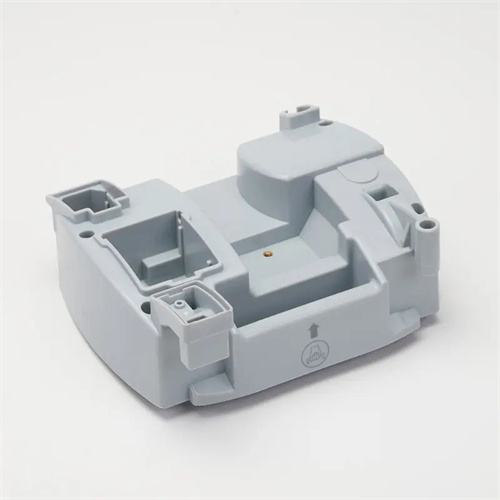
The process parameters for gas filling require precise control, including gas pressure, holding time, gas flow rate, and injection position. The synergistic effect of these parameters directly affects the filling effect. Gas pressure needs to be adjusted in stages. A lower pressure (5-10 MPa) is used during the initial injection phase to avoid impacting the melt and causing turbulence. The pressure is gradually increased to the set pressure (10-30 MPa) during the filling phase to ensure sufficient melt flow. During the holding phase, the pressure is maintained stable (5%-10% lower than the filling pressure) to compensate for part shrinkage. The holding time is determined based on the part’s wall thickness. For thick-walled parts (over 5 mm), the holding time is 15-20 seconds, while for thin-walled parts (under 2 mm), it is 5-10 seconds. For example, for an electrical housing with a 3 mm wall thickness, the holding time is set to 12 seconds to ensure that the gas effectively suppresses sink marks. Gas flow is controlled by a flow valve, typically at 5-15 L/min. Excessive flow can easily cause gas to penetrate the melt, while too little prevents the cavity from filling quickly. For example, when molding parts with deep ribs, a flow rate of 10 L/min is used to quickly push the melt to fill the ribs while preventing gas from penetrating. Injection is typically performed in the last area to be filled or in thick-walled areas, such as the end of a rib or in a corner, to ensure gas diffusion along the path of least resistance.
The design of gas filling equipment and mold structure is fundamental to process implementation. A dedicated gas generator, pressure control system, and mold gas flow channel are required. The gas generator is typically a nitrogen generator, capable of providing nitrogen with a purity exceeding 99.9% to prevent oxidation or degradation caused by reactions between oxygen and the melt. The pressure control system must feature multi-stage pressure regulation with a response time of no more than 0.1 second, ensuring pressure fluctuations are within ±0.5 MPa. The mold must be equipped with a gas injection nozzle with a diameter of 0.5-1.5 mm. The contact area with the molded part must be sealed to prevent gas leakage, such as a tapered sealing surface and a sealing ring to achieve a high-pressure seal. The gas flow channel should extend from the outside of the mold to the injection point, with a diameter of 3-6 mm. The interior of the channel must be smooth and free of burrs to reduce gas flow resistance. For large molds, multiple gas injection points can be installed. For example, a car bumper mold has three injection points, located at each end and in the center, to ensure even gas distribution. The pressure at each injection point can be independently adjusted to meet the filling requirements of different areas.
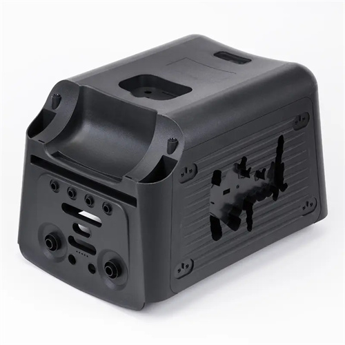
Gas filling offers significant advantages in addressing specific plastic part defects, effectively eliminating sink marks, reducing warpage, lowering internal stress, and improving surface quality and dimensional stability. For thick-walled parts (such as the thick protrusion on a TV back cover), traditional injection molding is prone to creating sink marks on the protrusion. However, with gas filling, the gas creates a pressure-maintaining effect within the protrusion, compensating for melt shrinkage and reducing sink mark depth from 0.3mm to below 0.05mm, meeting appearance requirements. In thin-walled part molding, gas filling reduces melt flow resistance, making it easier for the melt to fill thin-walled areas. For example, with a 1mm-thick laptop case, gas-assisted filling reduced the filling pressure from 150MPa to 100MPa without experiencing material shortages. Gas filling also reduces internal stress in the part. By evenly distributing the gas pressure, the melt experiences balanced stress during cooling. For example, in PC lens parts, internal stress has been reduced from 2MPa to below 0.5MPa, improving the lens’s impact resistance. In addition, gas filling can reduce the weight of plastic parts by 5%-15%. By forming a hollow structure inside the plastic parts, lightweighting can be achieved while ensuring strength. For example, the weight of a car dashboard can be reduced by 8%, which is beneficial to energy conservation and emission reduction.
Gas filling process control and troubleshooting common problems require extensive practical experience. Effective measures must be implemented to address issues such as gas penetration, surface gas marks, and underfill. Gas penetration is the most common problem, manifesting as gas bubbles forming on the surface of the part as it penetrates the melt. Solutions include reducing gas pressure (e.g., from 20 MPa to 15 MPa), delaying gas injection (e.g., from 70% to 80% fill), and reducing gas flow (e.g., from 12 L/min to 8 L/min). Surface gas marks are often caused by pressure shock during gas injection, which can be alleviated by optimizing the injection point (away from the exterior surface), increasing the melt temperature (e.g., by 5-10°C), and reducing the initial gas pressure (e.g., from 8 MPa to 5 MPa). Underfill may be caused by insufficient gas pressure or late injection. This requires increasing gas pressure (e.g., by 3-5 MPa), advancing injection time (e.g., from 85% to 75% fill), and checking for gas line blockages. For example, during gas filling, a plastic part experienced underfill at the edges. Inspection revealed impurities blocking the gas line. After cleaning, the gas pressure was increased by 2 MPa, resolving the underfill issue. By strictly controlling process parameters and promptly addressing abnormalities, the stability of the gas filling process can be significantly improved, reducing the defect rate to below 1%.