Injection molding uses inclined socket to pull off the water outlet material mechanism
In injection molding, sprue handling is a crucial step influencing production efficiency and product quality. The sprue-slug pull-off mechanism automatically separates the sprue, reducing manual labor and improving production automation. This mechanism, through the relative motion of the slug structure and the mold , applies tension to the sprue during mold opening, breaking it from the product. This mechanism is suitable for products with small gates, such as point gates and latent gates.
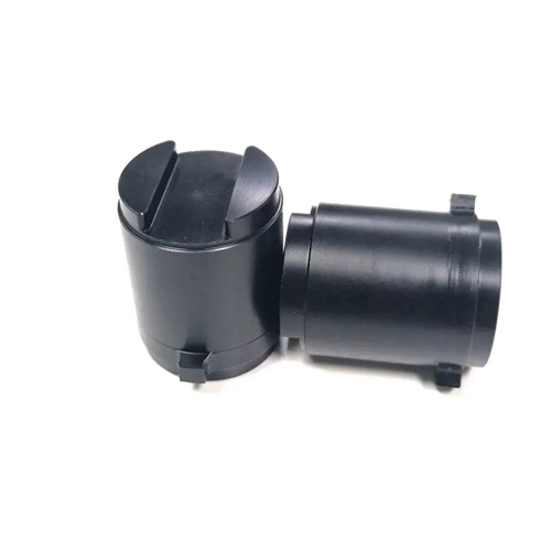
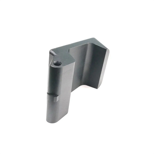
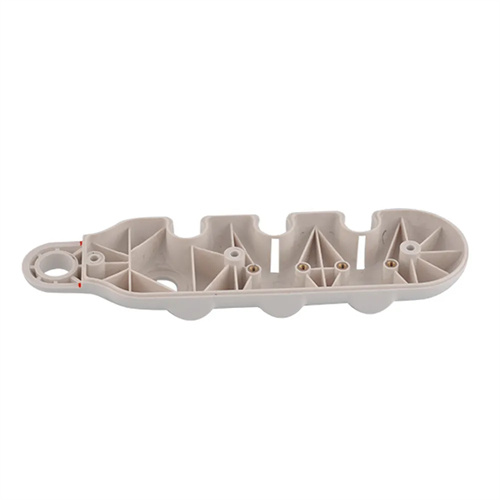
The core components of the inclined nest sprue material pulling and breaking mechanism include the inclined nest core, the pulling rod, the guiding mechanism and the resetting mechanism. These components work together to complete the pulling and breaking action of the sprue material. The inclined nest core is the component that is in direct contact with the sprue material. Its surface is provided with a conical or hemispherical groove. The groove depth is generally 1~3mm and the angle is 30°~60°. The sprue material is firmly held by friction. The pulling rod connects the inclined nest core to the movable mold part of the mold. When the mold is opened, it drives the inclined nest core to move backward and applies a pulling force to the sprue material. The guiding mechanism is usually a guide column and a guide sleeve to ensure the smooth movement of the inclined nest core and avoid failure of pulling and breaking caused by offset. The resetting mechanism generally uses a spring or a reset rod to push the inclined nest core back to its original position when the mold is closed, preparing for the next molding. For example, the inclined socket breaking mechanism of a certain point gate mold has an inclined socket core diameter of 8mm, a socket depth of 2mm, an angle of 45°, a pulling rod diameter of 10mm, and a spring force of 50N, which can reliably break a sprue material with a diameter of 3mm.
The sprue material break mechanism works based on relative motion during mold opening. When the mold begins to open, the movable mold moves backward, and the sprue core, driven by the pull rod, moves with it. The product on the fixed mold side is held stationary by the ejection mechanism or the cavity. At this point, the sprue material is subjected to tension from the sprue core and the restraining force of the product at both ends. When the tension exceeds the material’s strength limit, the sprue material breaks at the gate. After breaking, the sprue material continues to move backward with the sprue core, eventually falling off the core under the action of the ejection mechanism, completing automatic separation. To ensure effective breakage, the cross-sectional area at the gate should be as small as possible, generally between 0.5 and 2 mm². The groove of the sprue core should also provide sufficient friction. This can be achieved by increasing surface roughness or adding barbs to enhance the holding force. For example, a certain product uses a point gate with a diameter of 1mm, the surface roughness of the inclined core groove is Ra3.2μm, the mold opening speed is 50mm/s, and the breaking force is about 80N. The gate material can be broken within a distance of 10mm when the mold is opened.
The design of the mechanism for pulling off the sprue material with a slanted groove requires parameter optimization based on the gate type and sprue material size. Key parameters include the slant angle, groove depth, pull rod diameter, and mold opening speed. A slant angle that is too small will make the sprue material difficult to remove, while a larger angle will reduce the holding force. A range of 30° to 45° is generally recommended. The groove depth should be determined based on the sprue material diameter, typically 0.5 to 1 times the diameter, to ensure that the sprue material is firmly held without being too deep, making it difficult to remove. The pull rod diameter must meet strength requirements, typically 3 to 5 times the sprue material diameter, to avoid bending or breaking during the pulling process. The mold opening speed should be moderate. Too fast will cause the sprue material to be subjected to excessive force instantly, resulting in flash, while too slow will affect production efficiency. It is generally controlled within 30 to 80 mm/s. For example, a latent gate with a diameter of 2mm, a slant angle of 30°, a groove depth of 1.5mm, a pulling rod diameter of 8mm, and a mold opening speed of 60mm/s. After testing, the breaking effect is stable and the residual length of the gate material is less than 0.5mm.
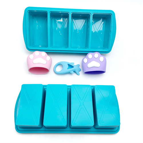
In practical applications, the oblique-nest sprue material pulling mechanism must be carefully coordinated with other mechanisms to avoid interference or uncoordinated movements. When working with the ejection mechanism, the ejection time should be later than the sprue material pulling time to ensure that the product is ejected after the pulling action is completed, avoiding premature ejection and resulting in pull-off failure. When working with the runner system, the runner should have a certain taper to facilitate the movement of the sprue material with the oblique-nest core. The taper is generally 1° to 3°. For multi-cavity molds, each oblique-nest pulling mechanism should be synchronized to ensure that each sprue material is pulled off simultaneously. Synchronous movement can be achieved through a unified pull rod fixing plate. For example, the oblique-nest pulling mechanism of a four-cavity mold uses an integral pull rod fixing plate to connect the four oblique-nest cores. When the mold is opened, the fixing plate drives each core to move simultaneously, and the pulling time deviation is controlled within 0.1 seconds to ensure consistent sprue material separation for each product.
Maintenance and upkeep of the sprue-slotting mechanism are crucial to its lifespan and operational stability. During daily use, the sprue-slotting core grooves should be regularly cleaned to remove residual plastic debris and prevent any loss of holding force. The pull rod and guide mechanism should also be regularly inspected for wear. Any bending or excessive play in the guides should be promptly replaced to prevent movement deviation. The return spring’s force gradually decreases with age and should be regularly tested. When it falls below 80% of the design value, the spring should be replaced. Furthermore, the sprue-slotting core should be cleaned before the mold is shut down to prevent residual plastic from adhering to the grooves after cooling and solidification. For example, one production line requires cleaning and inspection of the sprue-slotting mechanism every 500 molds and monthly replacement of the return spring. This keeps the mechanism’s failure rate below 0.5%, effectively ensuring production continuity.