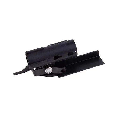
Injection molded through hole becomes blind hole
In injection molding, converting through-holes to blind holes involves optimizing the mold structure and adjusting the process. This technique involves converting the original through-hole design into a bottom-sealed blind hole to meet the assembly requirements of the plastic part or improve structural strength. This structural change is widely used in automotive parts, appliance housings, and other fields. For example, converting the mounting through-holes of an engine hood to blind holes can prevent oil leakage; converting the positioning through-holes of a mobile phone midframe to blind holes can enhance the impact resistance of the frame. Converting through-holes to blind holes is not a simple mold modification; factors such as melt flow, venting, and demolding efficiency must be comprehensively considered. Otherwise, defects such as pores, dents, or white spots can easily occur. For example, after converting the through-holes of an ABS appliance panel to blind holes, poor bottom venting caused bubbles to form at the bottom of the blind hole. This problem was resolved by adding a 0.01mm venting groove and fine-tuning the holding pressure parameters.
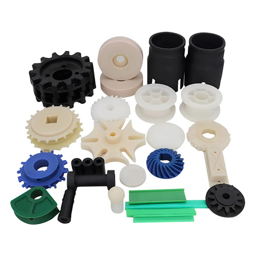
The structural design of the mold for converting through holes into blind holes needs to focus on optimizing the core and exhaust system. The bottom core of the blind hole needs to adopt a stepped structure, with a diameter 0.1-0.2mm smaller than the hole diameter, to reserve sufficient space for the melt to flow; an annular exhaust groove (depth 0.01-0.02mm) needs to be set at the root of the core, cooperating with the exhaust channel on the side of the cavity to ensure smooth exhaust of gas during melt filling. For blind holes with a depth exceeding 10mm, the core needs to be designed with a cooling water channel with a diameter of 8-10mm and a water flow rate controlled at 1.5-2m/s to avoid sticking of the plastic part due to overheating of the core. For example, in a blind hole gear mold made of polyoxymethylene (POM), the core has a built-in spiral cooling water channel to control the core temperature at 50-60℃, which shortens the cooling time at the bottom of the blind hole by 20%, effectively solving the problem of shrinkage depression.
Process parameter adjustments for converting through-holes to blind holes should focus on the filling and holding stages. During the filling phase, the injection speed should be reduced by 10%-15%, especially when the melt reaches the bottom of the blind hole. The speed should be controlled at 20-30 mm/s to prevent flash or bubbles caused by high-speed impact on the core. At the same time, the injection pressure should be increased by 5-10 MPa to ensure that the melt completely fills the corners of the blind hole. The holding phase should be staged. In the first stage (0-2 seconds), the holding pressure is 80%-85% of the injection pressure to prevent melt backflow. In the second stage (2-5 seconds), the pressure is reduced to 60%-70% to reduce internal stress at the bottom of the blind hole. For example, when producing polypropylene (PP) blind hole brackets, reducing the filling speed from 50 mm/s to 42 mm/s and increasing the injection pressure from 70 MPa to 75 MPa, combined with a two-stage holding pressure (60 MPa → 45 MPa), can increase the density of the blind hole bottom by 15%.
The demolding design for converting through-holes to blind holes must prevent deformation or damage to the plastic part. The draft angle of the blind hole core should be 0.5°-1° greater than that of the through-hole core, typically 1°-2°, to facilitate smooth part release. For blind holes with a depth-to-diameter ratio greater than 3:1, a titanium nitride (TiN) coating of 3-5μm thickness should be sprayed on the core surface to reduce the friction coefficient from 0.3 to below 0.15. The demolding mechanism can utilize a combined ejector tube and ejector plate design. The ejector tube fits over the core, with an ejection stroke 1-2mm longer than the core, ensuring that the plastic part is released from the core before being ejected as a whole. For example, in the demolding of blind holes in polycarbonate (PC) lampshades, a 0.02mm precision ejector tube combined with a 1.5° draft angle reduces the demolding force by 30%, preventing damage to the blind hole’s inner wall.
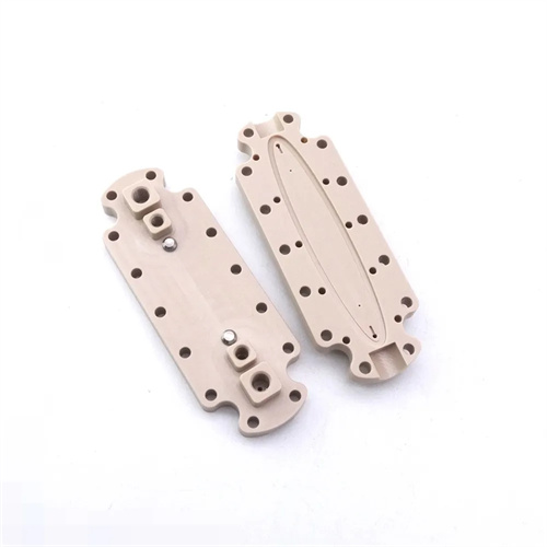
Quality inspection of through-hole-to-blind-hole conversions requires attention to bottom thickness and internal defects. An ultrasonic flaw detector is used to test the bottom of the blind hole for tightness, ensuring the absence of air holes or shrinkage. A three-dimensional coordinate measuring machine is used to measure the bottom thickness, with a deviation within ±0.05mm to prevent strength deficiencies caused by uneven thickness. For plastic parts with high aesthetic requirements (such as transparent ABS blind-hole decorative parts), an optical microscope (50x magnification) is used to inspect the bottom for weld marks or silver streaks. For example, during the inspection of a blind-hole component in an automotive interior, ultrasonic testing revealed a 0.2mm air hole at the bottom. After optimizing the venting groove depth to 0.015mm and extending the hold time by 2 seconds, the defect was completely eliminated. With the application of 3D printing technology, a core design with conformal cooling can be used to improve temperature uniformity at the bottom of the blind hole by 40%, further ensuring molding quality.