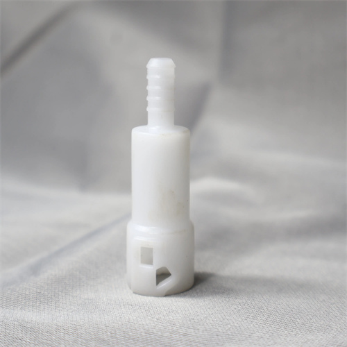
Injection molded push tube design
The injection molding ejector tube (also known as a hollow ejector rod) is a mold release component designed for tubular, cylindrical, or perforated plastic parts. Its hollow structure fits over the mold core, enabling synchronous ejection along the core axis, effectively preventing deformation or damage to the part caused by uneven force during demolding. The core of the ejector tube design is to ensure precise fit with the mold core and mold plate, while also balancing ejection stability and process feasibility. It is widely used in the production of plastic parts such as bearing sleeves, bolt sleeves, and beverage bottle preforms. For example, in PET preform molds, the ejector tube’s concentricity error must be controlled within 0.02mm. Otherwise, the preform mouth will become oval or scratched, affecting the sealing performance during subsequent blow molding.
The push tube’s structural dimensions must be precisely matched to the part and core parameters. The inner diameter should be 0.05-0.1mm larger than the core diameter to ensure friction during ejection. The outer diameter should be 0.02-0.05mm smaller than the part’s inner diameter to prevent scratching of the part’s inner wall during ejection. The push tube’s length should cover the part’s molding height on the core, and guide sections (1-1.5 times the diameter) should be reserved at both ends to enhance stability. For slender push tubes (length-to-diameter ratio > 15), a central guide sleeve made of bronze or wear-resistant cast iron is required to reduce the risk of bending. For example, when producing a PA66 bearing sleeve with a length of 100mm and an inner diameter of 10mm, the push tube is designed with an inner diameter of 10.08mm, an outer diameter of 12mm, and an overall length of 120mm. Combined with the central bronze guide sleeve, this eliminates any sticking during ejection.
The material selection and heat treatment process for push tubes directly impact their service life. Conventional push tubes are made of T8A carbon tool steel, which undergoes a quenching treatment (hardness HRC 50-55) and is suitable for small-batch production. Large-scale production (>500,000 molds) requires Cr12MoV alloy tool steel, which achieves a hardness of HRC 58-62 after through-hardening. Both internal and external surfaces are ground to a roughness of Ra ≤ 0.4μm. The cutting edge of the push tube (the contact point with the plastic part) requires a radius (R 0.1-0.3mm) to prevent sharp edges from scratching the part. For example, a mold for an automotive water pipe connector uses Cr12MoV push tubes. After cryogenic treatment (-80°C), the wear resistance of the cutting edge is increased by 40%, resulting in a service life of 800,000 molds, far exceeding the 300,000 molds of the T8A push tube.
The design of the mating structure between the push tube and the mold must meet guidance and exhaust requirements. The push tube and push plate are typically connected using a stepped fixation. A countersunk hole is set at the end of the push plate with a depth of 0.8-1 times the diameter of the push tube, and a locating pin is used to prevent rotation. A gap of 0.01-0.03mm is required between the push tube and the cavity plate, which also serves as an exhaust channel. For plastics that easily generate gas (such as PVC and POM), exhaust grooves (1mm wide, 0.02mm deep, and 5mm long) are required on the outer wall of the push tube to enhance the exhaust effect. For example, in a PVC pipe fitting mold, four exhaust grooves are symmetrically opened on the outer wall of the push tube, combined with a 0.02mm clearance, successfully solving the problem of bubbles at the bottom of the pipe fitting.
The design of the push tube must consider the shrinkage characteristics of the plastic part and the demolding angle. For crystalline plastics (such as PP and PE), due to their high shrinkage (1%-3%), the ejection position of the push tube should avoid areas of concentrated shrinkage stress in the plastic part. It is usually located near the flange or rib of the plastic part. The ejection stroke of the push tube should be 1-2mm longer than the wrap length of the plastic part on the core to ensure complete demolding. When the plastic part has an undercut, it must be used in conjunction with a core pulling mechanism. The core pulling action must be completed before the push tube is ejected to avoid interference. For example, when producing PP bottle caps with internal threads, the push tube is designed as a two-stage push tube. The thread core pulling mechanism first unscrews the threads, and then the push tube ejects the bottle cap. The ejection stroke is 1.5mm longer than the thread length to ensure complete demolding. With the advancement of mold CAD technology, push tube design can verify the motion trajectory through 3D simulation, identify interference issues in advance, and reduce mold trial adjustment time by over 30%.