The structure of injection molding push rod
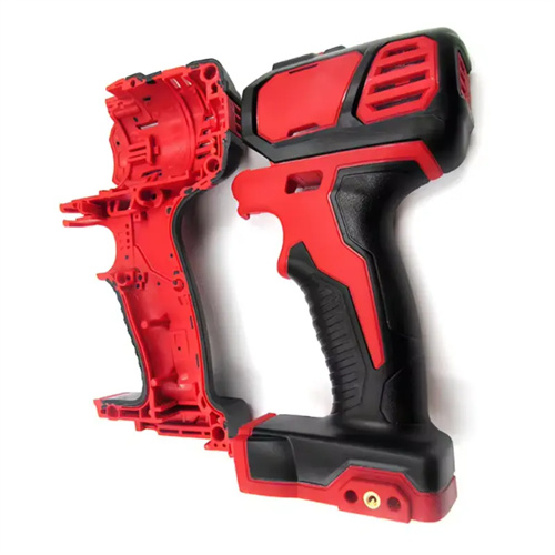
The injection molding push rod is the most widely used component in the mold ejection mechanism, and its structure directly impacts the part’s demolding quality, surface quality, and production efficiency. The push rod’s primary function is to eject the plastic part from the cavity or core after mold opening. Depending on the part’s material, shape, size, and surface requirements, different structures are selected to prevent defects such as whitening, deformation, and scratches. For example, for high-gloss plastic parts (such as PMMA lampshades) where ejection marks are unacceptable, a contoured push rod that conforms to the part’s curved surface is required. For thinner-walled parts (such as PP sheets), a large, disc-shaped push rod is required to prevent breakage during ejection. Choosing the right push rod structure is essential for smooth injection molding production.
The straight-through push rod is the most commonly used basic structural form. Its characteristic is that the rod body is a cylindrical rod with a constant diameter, one end connected to the push plate, and the other end directly acting on the plastic part. Straight-through push rods are categorized by diameter as small (φ3-φ8mm), medium (φ10-φ20mm), and large (φ25-φ50mm). They are suitable for plastic parts with simple structures and low surface requirements. Small push rods are often used to eject ribs or bosses in plastic parts and require a guide sleeve to prevent bending. Medium push rods are suitable for ejecting general plastic parts and require a tempered rod body (hardness HRC 28-32) with a surface roughness Ra ≤ 0.8μm. Large push rods are used for ejecting large plastic parts and require a hardened rod end (hardness HRC 45-50) to prevent deformation from long-term use. For example, when producing ABS toy shells, six φ8mm straight-through push rods are used, evenly distributed around the edge of the plastic part, ensuring stable ejection force and preventing whitening.
Stepped push rods are suitable for complex plastic parts requiring ejection force at different locations. Their rod diameter varies in steps along its length, typically with a smaller diameter (φ5-φ12mm) at the end closest to the part and a larger diameter (φ15-φ30mm) at the end connecting to the push plate. This ensures flexibility in applying force to the part while improving overall rigidity. The steps of the stepped push rods require a rounded transition (radius R ≥ 2mm) to avoid stress concentration that could lead to fracture. The mating section between the rod and the mold plate is ground, with a clearance of 0.02-0.05mm. For example, in the production of PC appliance housings with deep cavities and bosses, three stepped push rods (φ8mm × φ16mm) are used to eject the deep cavity, while four straight-through push rods are used to eject the edges, successfully resolving the mold release challenges in these deep cavities.
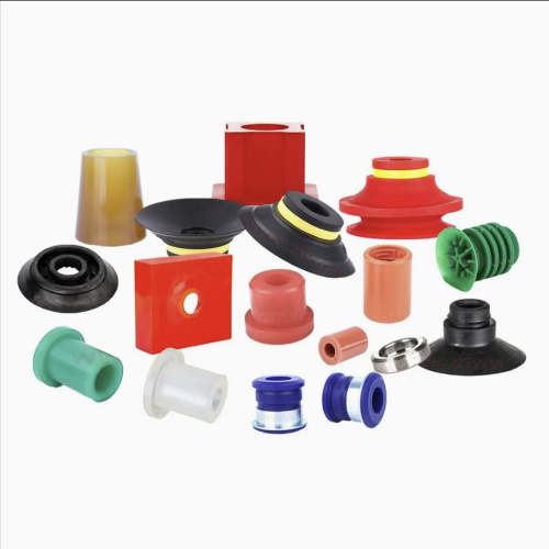
Special-shaped ejectors are non-standard designs for specialized plastic part structures. Common types include tapered, disc, and flat pushers. Tapered pushers feature a conical tip (taper of 1:5-1:10) and are suitable for ejecting tapered holes or recesses in plastic parts, minimizing surface damage. Disc pushers have a disc-shaped tip (diameter φ20-φ100mm) with a large contact area, making them suitable for ejecting thin-walled parts (thickness <1mm) or soft plastics (such as PE and PP), preventing deformation during ejection. Flat pushers have a rectangular cross-section (width 10-30mm, thickness 3-8mm) and are suitable for ejecting narrow, elongated parts or ribbed sections. For example, when producing a 0.5mm-thick PE film part, using three disc-shaped ejectors with a diameter of φ50mm ensures uniform force during ejection, keeping part flatness tolerances within 0.1mm.
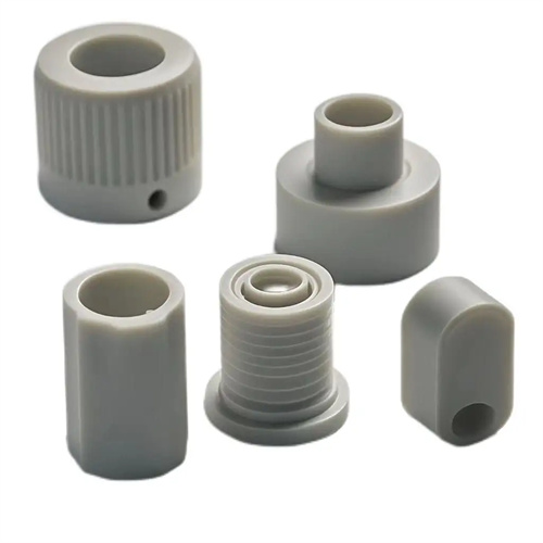
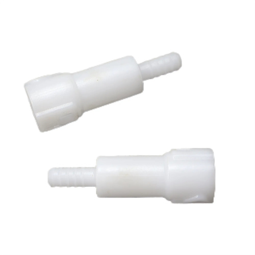
Hollow push rods (also known as push tubes) are suitable for ejecting plastic parts with holes or tubular shapes. They are hollow cylinders with their inner wall fitting over the core and their outer wall contacting the part, preventing frictional damage from the core during ejection. The push tube’s inner diameter should be 0.05-0.1mm larger than the core diameter, and its outer diameter should be 0.02-0.05mm smaller than the part’s hole diameter to ensure smooth ejection without scratching the hole wall. The push tube’s length should generally not exceed 15 times its diameter; any longer than this requires a guide. The material typically used is Cr12MoV, which is quenched (HRC 55-60 hardness) and has an inner wall roughness of Ra ≤ 0.4μm. For example, when producing PA66 bolt sleeves, a φ12mm × φ10mm hollow push rod with an inner and outer clearance of 0.08mm achieves an inner hole surface roughness of Ra 1.6μm after ejection, meeting assembly requirements.
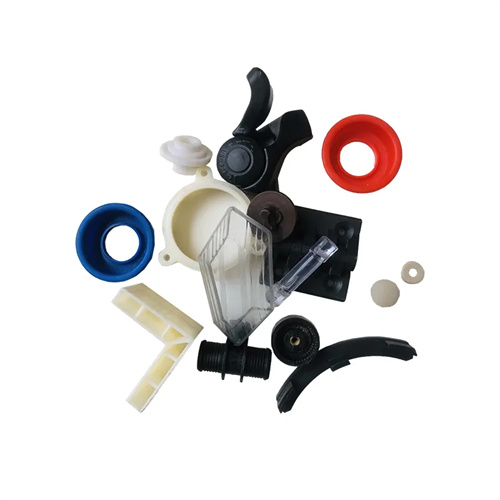
Combination push rods combine multiple push rod structures and are suitable for demolding complex-shaped plastic parts. Common combinations include “straight-through push rod + special-shaped push rod” and “push rod + push plate.” The design of combination push rods must adhere to the principles of “even distribution and proximity.” The ejection point should be located near rigid areas of the part (such as thick walls and the base of ribs), avoiding weak areas. For example, in the production of an automotive instrument panel (PP + GF30), 12 straight-through push rods (φ10mm) are used to eject the edges, four disc-shaped push rods (φ30mm) are used to eject large flat surfaces, and two flat push rods are used to eject the instrument panel’s ribs. This synergistic effect ensures smooth demolding of the part, achieving a flatness error of ≤0.5mm after ejection. With the application of 3D printing technology, combination push rods can be customized to the part’s shape, further improving ejection accuracy and reliability and reducing ejection defects.