Injection molding inclined wedge slider type secondary demoulding mechanism
The injection molding secondary demolding mechanism with a wedge-shaped slider is a precision mold structure designed to address the demolding challenges of complex plastic parts. It is primarily suitable for parts with deep cavities, undercuts, or complex curved surfaces. Through two distinct demolding motions, the part is smoothly released from the mold cavity. This mechanism utilizes the inclined surface of the wedge to drive the slider, shifting the demolding force and direction of movement. The first demolding motion typically releases the part from the mold cavity, while the second demolding motion completely ejects the part from the core or ejector, preventing deformation or damage during demolding. Compared to traditional single-stage demolding mechanisms, the wedge-shaped slider secondary demolding mechanism offers advantages such as smooth motion, controllable demolding force, and a wide range of applications. It is widely used in the production of precision plastic parts such as automotive parts and appliance housings.
The structure of a secondary ejection mechanism using a cam and slider is relatively complex, consisting of key components such as a cam, slider, ejector plate, push rod, and reset mechanism. The cam is typically fixed to the mold plate of the movable or fixed mold. Its working surface is an inclined plane or curved surface. By contacting the inclined surface of the slider, it converts the linear motion of the mold opening and closing into lateral or vertical motion of the slider. The slider is the core actuator of the mechanism, connected to the push rod or ejector, directly acting on the plastic part to achieve demolding. Its bottom is typically equipped with a guide groove that mates with the guide posts on the mold plate to ensure precise movement. The ejector plate is divided into a primary ejection plate and a secondary ejection plate, respectively controlling the sequence and stroke of the two ejection operations. The two plates are connected by a tie rod, spring, or hydraulic cylinder to achieve orderly movement. The reset mechanism, typically a reset spring or reset rod, returns the mechanism to its initial position after ejection is complete, preparing for the next molding cycle. In addition, some mechanisms also have limiters to control the slider’s travel to prevent damage to components due to excessive movement.
The operating principle of the cam-and-slide secondary ejection mechanism is based on the principles of inclined plane transmission and motion superposition. During the mold opening process, the mold first performs the initial mold opening motion, separating the movable mold from the fixed mold. At this point, the cam fixed to the fixed mold begins to contact the slider, pushing the slider laterally along the guide groove, driving the push rod to perform the initial ejection of the plastic part, separating the part from the cavity surface and relieving most of the clamping force. When the initial ejection reaches the preset stroke, the limiter engages, stopping the slider’s lateral movement. The ejector plate then drives the push rod to perform the second ejection, completely ejecting the part from the core or cam, completing the ejection process. During the mold closing process, the reset device resets the ejector plate and slider, gradually disengaging the cam and slider, and ultimately returning all components to their initial positions, ready for the next injection cycle. Throughout this process, the sequence and stroke of the two ejection motions are precisely controlled by the mechanism’s dimensional design and limiters, ensuring uniform force distribution during the ejection process and preventing deformation or scratches.
The key design considerations for a secondary ejection mechanism with a wedge and slider are ensuring coordinated and reliable movement. The angle of the wedge is a critical parameter. A too small angle results in insufficient slider travel, while a large angle increases the positive pressure between the wedge and slider, increasing friction loss and driving force requirements. Typical values range from 15° to 25°. The contact surface between the slider and the wedge must be precision machined to a surface roughness Ra of no greater than 0.8μm. A reasonable clearance, typically 0.02-0.05mm, should be established to reduce friction and ensure smooth movement. The stroke design of the mechanism should be determined based on the structural characteristics of the plastic part. The initial ejection stroke should allow the part to completely exit the mold cavity, typically 1/3-1/2 of the part’s height. The secondary ejection stroke should ensure smooth part removal, typically 5-10mm greater than the part’s maximum height. Furthermore, the positioning and spring force of the reset mechanism must be carefully considered to ensure accurate reset during mold closing while avoiding excessive reset force that could cause part deformation.
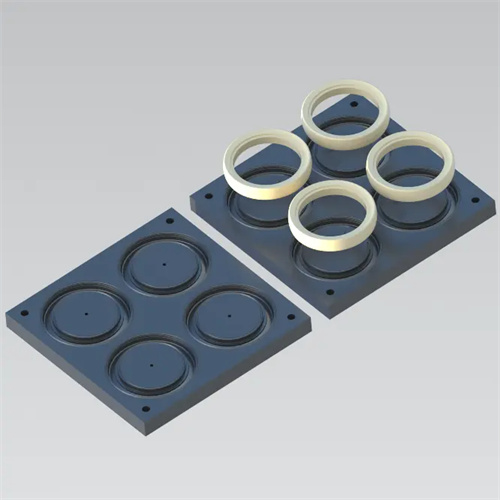
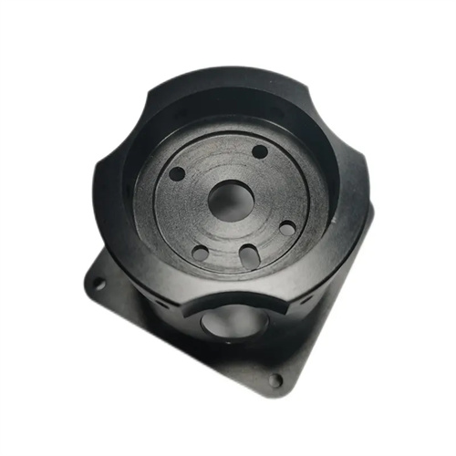
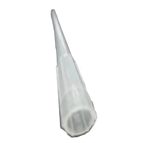
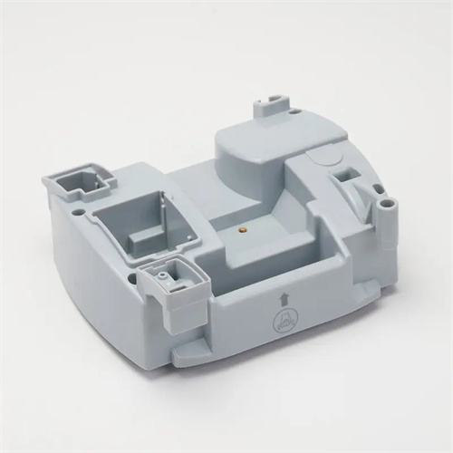
The application of a secondary ejection mechanism with a wedge and slider requires optimized design based on the specific characteristics of the plastic part. For deep-cavity parts, such as plastic barrels and containers, the initial ejection stroke should be increased to reduce the contact area between the part and the cavity and thus the clamping force. Furthermore, the connection between the slider and the push rod should be rigid to prevent deformation during ejection. For parts with undercuts, such as electrical switch housings, a core-pulling mechanism corresponding to the undercut can be incorporated into the slider. This allows the undercut to be pulled during the first ejection and the part to be ejected during the second ejection. In high-speed injection molding, the mechanism’s response speed needs to be improved. Wear-resistant materials such as Cr12MoV can be used for the wedge and slider, and nitriding can be performed to enhance surface hardness and wear resistance. Furthermore, for large parts, multiple sets of wedge and slider mechanisms can be symmetrically arranged to ensure even release force distribution and prevent part deflection during ejection. Furthermore, a good lubrication and cooling system should be implemented for the moving parts of the mechanism to reduce frictional heat generation, extend the mechanism’s service life, and ensure stable and continuous production.