Design of injection mold gate sleeve
The injection mold sprue bushing is a critical component connecting the injection molding machine nozzle to the mold cavity. Its design quality directly impacts the flow properties of the plastic melt, molding efficiency, and the quality and stability of the molded part. The sprue bushing’s material selection and heat treatment process are key design considerations. Because the sprue bushing is in constant contact with the high-temperature, high-pressure melt and must withstand the repeated impact and friction of the injection molding machine nozzle, it must be made of a material with high strength, high wear resistance, and excellent heat resistance. Commonly used materials include carbon tool steels such as 45 steel, T8, and T10. 45 steel, after quenching and tempering, can meet general operating requirements. However, for high-volume molding or processing of highly abrasive plastics (such as glass fiber reinforced plastics), alloy tool steels such as Cr12 and Cr12MoV are required. These steels should be quenched to a surface hardness of 50-55 HRC to extend their service life. In addition, the spherical surface where the gate sleeve contacts the nozzle should be finely ground to ensure that the surface roughness Ra ≤ 0.8 μm to reduce the melt flow resistance and avoid leakage.
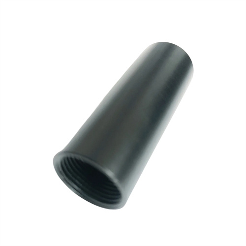
The sprue bushing’s structural dimensions must match the injection molding machine nozzle and mold sprue to ensure smooth melt flow. The sprue bushing’s inlet is typically designed as a spherical concave recess. Its radius should be 1-2 mm larger than the nozzle’s to ensure a good fit and prevent melt leakage. The inlet diameter should be 0.5-1 mm larger than the nozzle aperture to avoid melt flow obstruction caused by dimensional mismatch. The sprue bushing’s taper angle is also crucial, typically ranging from 2° to 6°. A too small taper angle increases melt flow resistance, while a too large one causes the melt in the runner to cool too quickly, affecting filling efficiency. The sprue bushing’s length should be kept as short as possible, typically between 60 and 100 mm. Excessive length can cause the melt temperature to drop excessively during flow, increasing scrap. Furthermore, the sprue bushing’s positioning must be appropriate. Typically, the sprue bushing is axially positioned by means of a shoulder that mates with a countersunk hole in the fixed platen. It is then secured with hexagon socket head cap screws to prevent displacement during the injection molding process.
The precise fit of the sprue bushing with other mold components is crucial for ensuring molding stability. A transition fit of H7/m6 is typically used between the sprue bushing and the fixed platen, ensuring both secure assembly and ease of disassembly and replacement. The transition between the main runner bushing and the branch runner should be smooth, avoiding right angles or steps. These can cause eddy currents and pressure loss in the melt flow, impairing filling efficiency. Furthermore, the sprue bushing’s outlet should connect smoothly to the cavity. If point gating is used, a small gate hole should be machined into the end of the sprue bushing. The diameter is determined by the part size and raw material characteristics, generally ranging from 0.5-2mm, and the hole’s axis should be perpendicular to the cavity surface to ensure uniform melt entry. For large parts or multi-cavity molds, a multiple sprue bushing design may be necessary. In this case, the sprue bushings should be symmetrically distributed to ensure simultaneous melt flow to all areas of the cavity.
Although easily overlooked, the cooling and venting design of the sprue bushing is crucial for improving production efficiency and part quality. Because the sprue bushing is constantly exposed to the high-temperature melt, excessively high temperatures can cause the melt to cool prematurely or decompose within the flow channel. Therefore, for molds molding heat-sensitive plastics (such as PVC) or for high-speed molding, cooling water channels are required around the sprue bushing. The cooling water channels should be located close to the outer surface of the sprue bushing, but should avoid interference with the fixing screws and locating holes. Annular or spiral channels are typically used to ensure uniform cooling. Furthermore, air easily accumulates at the contact point between the sprue bushing and the nozzle. If not promptly exhausted, this can lead to air streaks or material shortages during the initial melt filling phase. Therefore, a tiny venting groove, typically 0.5-1mm wide and 0.02-0.05mm deep, can be created in the spherical concave portion of the sprue bushing. This effectively vents the air without causing melt leakage.
The design of the sprue bushing also needs to consider mold usability and maintenance costs. In actual production, the sprue bushing is a vulnerable component that requires regular replacement. Therefore, its structure should be easy to remove and install. For example, the press-in length of a sprue bushing should be moderate. Too short will result in an unstable installation, while too long will increase the difficulty of removal. For molds that require frequent replacement, a replaceable sprue bushing can be designed, connecting to the fixed platen via threads or snaps to reduce replacement time. In addition, the inner wall of the runner of the sprue bushing should be polished to reduce surface roughness, thereby reducing melt flow resistance and retention, and facilitating the removal of residual material in the runner. The design also needs to consider the ease of waste removal. For molds with long sprue channels, a pull rod can be installed at the end of the sprue bushing to eject the sprue along with the molded part, improving production efficiency. In short, the design of the sprue bushing requires comprehensive consideration of multiple factors, including material properties, structural dimensions, fit accuracy, cooling and exhaust, and maintenance, to ensure stable and reliable operation during the injection molding process.