Common defects of injection molding products and solutions
During the production process of injection molded products, various quality defects, such as surface sink marks, flash, weld marks, and bubbles, are inevitable due to factors such as raw materials, equipment, processes, and molds. These defects not only affect the product’s appearance but may also reduce its mechanical properties and safety. Different defect types require in-depth analysis of their causes and targeted solutions to effectively improve product qualification rates. For example, sink marks are often associated with insufficient holding pressure, while flash can be caused by insufficient clamping force or excessive injection pressure. Therefore, establishing a comprehensive defect analysis and resolution system is crucial for improving production efficiency, reducing costs, and ensuring product quality.
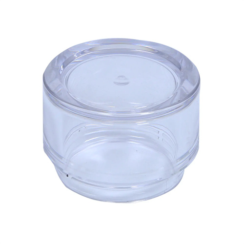
Surface sink marks are one of the most common defects in injection molded parts. They appear as depressions or craters on the part surface, often occurring in areas with uneven wall thickness, at the base of ribs, or near the gate. The primary cause of sink marks is uneven melt shrinkage during cooling. Thick-walled areas shrink more than thin-walled areas due to slower cooling, leading to a failure to compensate for shrinkage during the holding phase. Addressing sink marks requires addressing both process parameters and mold design. For example, increasing the holding pressure (typically 70%-80% of the injection pressure) and extending the holding time can ensure adequate compensation in thick-walled areas. For example, for ABS parts, increasing the holding time from 5 seconds to 7 seconds while increasing the holding pressure by 10%-15% can also be helpful. Appropriately increasing barrel and mold temperatures can reduce melt viscosity and enhance compensation. In mold design, auxiliary gates can be placed in thick-walled areas to shorten melt flow distance. Increased radiused corners at the base of ribs can reduce sudden changes in wall thickness. Optimizing the cooling system by adding cooling water channels to thick-walled areas can accelerate cooling. In addition, reducing the amount of release agent used can also alleviate sink marks, because excessive release agent will affect the fluidity of the melt and the shrinkage feeding effect.
Flash (also known as flash) refers to an unwanted thin edge on the edge of a part. It’s primarily caused by excessive gaps between the mold parting surface or between inserts, allowing the melt to escape through the gap under injection pressure. Flash is closely related to factors such as insufficient clamping force, excessive injection pressure, and low mold precision. To address flash, first inspect the mold and polish the parting surface to ensure a tight fit, with the gap controlled within 0.02mm. Tighten the inserts and guide pins and bushings to prevent loosening and increased gaps. To adjust process parameters, reduce injection and holding pressures. For example, for PC parts, reduce the injection pressure from 150MPa to 130MPa, and the holding pressure from 100MPa to 80MPa. Reduce the injection speed, especially near the parting surface, to minimize the impact of the melt on the mold. If flash occurs only in specific areas, it may be because the mold temperature in that area is too high, causing the gap to expand due to thermal expansion. In this case, reduce the mold temperature in that area, such as by adjusting the cooling water flow rate to lower the local temperature by 5-10°C. For flash caused by insufficient clamping force, it is necessary to replace the injection molding machine with a larger tonnage to ensure that the clamping force is greater than 1.2-1.5 times the cavity pressure.

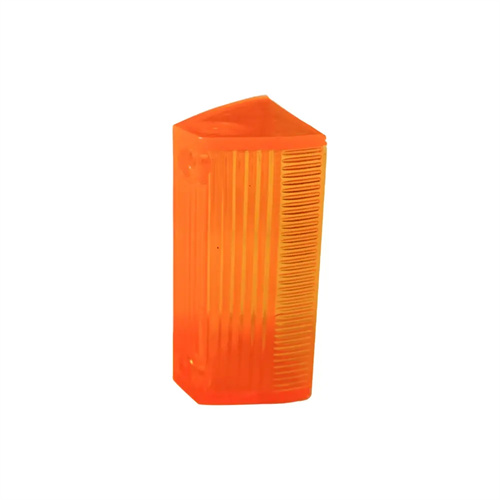
Weld marks are formed when the melt splits and then rejoins in the mold cavity. They appear as lines or areas on the part’s surface, affecting not only its appearance but also potentially reducing local strength. Weld marks are associated with factors such as low melt temperature, poor fluidity, and poor venting. The key to resolving weld marks is improving the melt’s ability to fuse. This can be addressed by increasing barrel and mold temperatures. For example, for PP products, raising the barrel temperature from 200°C to 220°C and the mold temperature from 40°C to 60°C can enhance melt fluidity and thermal stability. Optimizing the injection speed, such as using high-speed injection at the weld mark location, increases the melt’s impact kinetic energy and promotes molecular fusion. In mold design, optimally arrange gate placement to minimize melt splitting. For example, switching from a multi-point gate to a single-point gate ensures the melt fills the cavity in a single direction. Add venting grooves with a depth of 0.02-0.03mm and a width of 5-10mm at the weld mark location to ensure smooth gas discharge and prevent air bubbles from being trapped at the weld. In addition, adding an appropriate amount of plasticizer or lubricant to improve the fluidity of the plastic can also reduce the obviousness of the weld mark.
Air bubbles (also known as cavitation) are cavities that appear inside or on the surface of a product. They are primarily caused by gases in the melt not being released in time or by moisture or volatiles in the raw materials. The formation of air bubbles can reduce the mechanical properties of the product, particularly in stress-bearing areas, where they can cause fracture. Solutions for air bubbles require both raw material pretreatment and process adjustments. For raw materials, thoroughly dry highly hygroscopic plastics (such as PA and PC) at 80-100°C for 4-6 hours for PA and 120-140°C for 6-8 hours for PC, ensuring the moisture content is below 0.05%. Reduce the proportion of regrind, as regrind can contain volatiles and impurities, increasing the risk of air bubbles. For process control, increase the barrel temperature to allow volatiles to escape before injection, but be careful not to overheat to prevent plastic degradation. Reduce the injection speed, especially during the initial filling phase, to facilitate air evacuation. Extend the hold time to compact the melt and reduce internal voids. In mold design, increase the number and size of venting slots, especially where the melt is last filled. Optimize gate placement to prevent air from being trapped in the melt . For example, use an edge gate instead of a center gate to reduce air entrapment. Also, check the clearance between the screw and barrel. If the clearance is too large, air can be introduced into the melt, requiring prompt replacement of worn screws or barrels.

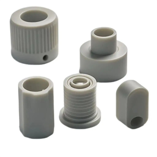
Warpage is a shape deviation such as bending and twisting that occurs after the product cools. It is mainly caused by uneven shrinkage or excessive internal stress in various parts of the product. It is common in thin-walled, large-area or uneven-wall-thick products. Warpage can affect the assembly performance and usability of the product and, in severe cases, can lead to product scrapping. The solution to warpage should start with reducing internal stress and uneven shrinkage: in terms of process, optimize the cooling system to ensure uniform cooling of all parts of the product. For example, set up independent cooling water channels in different areas of the mold and control the cooling speed of each area by adjusting the flow rate; reduce the injection pressure and holding pressure to reduce the residual stress inside the product. For example, reduce the injection pressure of POM products from 120MPa to 100MPa, and the holding pressure from 80MPa to 60MPa; extend the cooling time to allow the product to fully cool and set before demolding to avoid further shrinkage due to temperature differences after demolding. In mold design, a symmetrical structure is adopted to reduce wall thickness differences, for example, the wall thickness tolerance of the product is controlled within ±0.1mm; reinforcing ribs are set in areas prone to warping to improve structural rigidity; the gate position is optimized to ensure uniform melt filling and reduce internal stress in the flow direction.