Classification of lateral parting and core pulling mechanisms
Lateral parting and core pulling mechanisms are key components in injection molds for handling lateral bumps or holes in plastic parts. Depending on the power source, these mechanisms can be categorized as manual. These mechanisms rely primarily on manual operation to perform parting and core pulling, making them suitable for small- batch production or for parts with simple structures. Manual mechanisms can be further categorized as in-mold and out-mold. In-mold manual mechanisms typically incorporate operating components such as handles and screws within the mold. After the mold is opened, rotating the handle drives the core pulling element, completing the core pulling process. In-mold manual mechanisms, however, manually remove the lateral core from the part after mold opening and re-insert it into the mold before closing. While these mechanisms offer advantages such as a simple structure and low manufacturing cost, they also offer disadvantages such as low production efficiency, high labor intensity, and the accuracy of core pulling can be easily affected by human factors. For example, for small, lateral holes in small electrical appliance parts, a manual screw-type core pulling mechanism can reduce mold costs if the production batch is small. However, this requires manual operation for each piece, making it difficult to adapt to large-scale production.
Hydraulic or pneumatic side-parting and core-pulling mechanisms are currently the most widely used. Powered by a hydraulic pump or air compressor, these mechanisms operate via hydraulic or pneumatic cylinders, driving the core-pulling components. These mechanisms offer high core-pulling force, long core-pulling distance, smooth operation, and precise control of speed and stroke, making them suitable for the production of large and complex plastic parts. Based on the installation location of the hydraulic or pneumatic cylinder, they can be categorized as either internal or external. Internal installations feature the hydraulic or pneumatic cylinder inside the mold, resulting in a compact design and minimal space. External installations, however, are externally mounted, offering easy maintenance but requiring more space. Compared to pneumatic systems, hydraulic systems offer greater core-pulling force and more flexible speed adjustment, making them suitable for applications requiring high core-pulling force, such as side-parting of large automotive parts. Pneumatic systems offer lower costs and faster response times, but with relatively low core-pulling force, making them suitable for small and medium-sized parts. For example, when producing washing machine parts with deep side holes, a hydraulic internal core-pulling mechanism provides stable core-pulling force, ensuring high-quality side-hole molding.
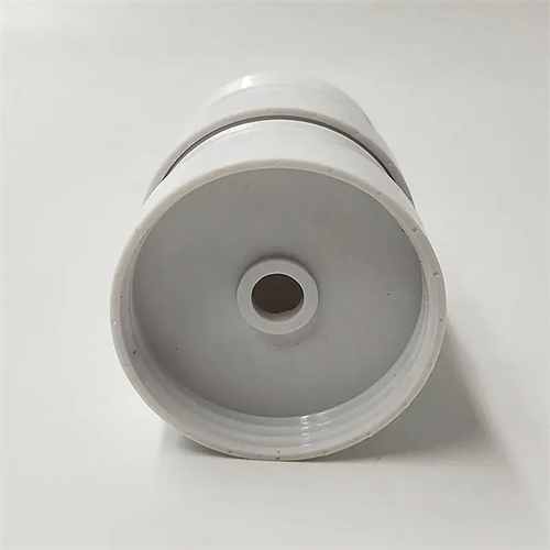
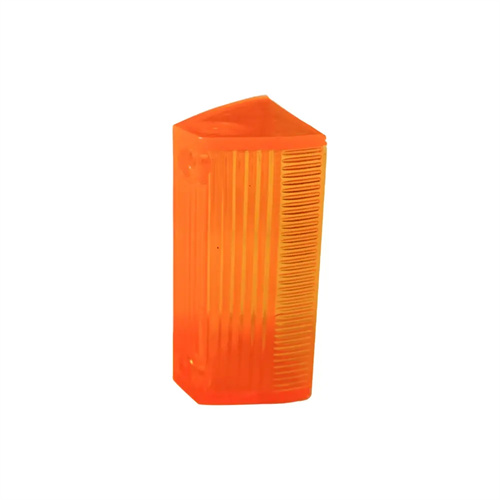
Mechanical lateral parting and core pulling mechanisms rely on the power of the mold opening or closing, achieving core pulling through mechanical transmission components. Common types include inclined guide pins, inclined sliders, and rack and pinion types. The inclined guide pin type is the most widely used, consisting of an inclined guide pin, a side core slider, and a guide chute. During mold opening, the movable and fixed molds separate, and the inclined guide pins move relative to the sliders, forcing the sliders to move laterally along the guide chute to complete core pulling. Its simple structure, ease of manufacture, and reliable operation make it suitable for applications requiring low core pulling forces and short core pulling distances, such as lateral boss molding for small and medium-sized plastic parts. The inclined slider type integrates the side core and inclined slider into one unit. During mold opening, the inclined slider, driven by the movable mold, moves along the inclined guide chute, simultaneously completing parting and core pulling. This makes it suitable for applications with concave and convex structures on the outside of the plastic part, providing smooth core pulling and high-quality molding. The rack and pinion mechanism realizes core pulling through the meshing transmission of the gear and rack. It has a large core pulling distance and high precision. It is often used in situations where circular side holes or multi-directional core pulling are required, such as lateral core pulling of pipe fittings and plastic parts.
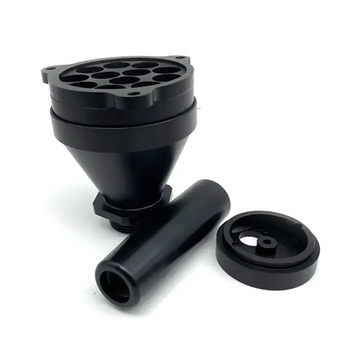
Depending on the direction and number of core pulling, lateral parting and core pulling mechanisms can be categorized as single-parting-surface, double-parting-surface, and multi-directional. Single-parting-surface mechanisms are simple, with the core pulling mechanism located on only one parting surface. They are suitable for parts with lateral projections and recesses in a single direction. Double-parting-surface mechanisms require the coordination of two parting surfaces to achieve core pulling. They are typically used for complex parts where a single parting surface cannot achieve the required core pulling. For example, when a part has both lateral holes and internal bosses, core pulling in different directions is required by sequentially operating the two parting surfaces. Multi-directional mechanisms can achieve core pulling in multiple directions simultaneously or sequentially. They are suitable for complex parts with multiple lateral projections and recesses or holes, such as multi-port plastic parts in medical devices, which require core pulling mechanisms in multiple directions, such as vertical, horizontal, and vertical. These mechanisms typically consist of multiple core pulling units, coordinated through a linkage mechanism. While complex in structure, they can meet the molding requirements of complex parts.
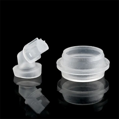
Based on the movement of the core-pulling components, lateral parting and core-pulling mechanisms can be categorized as linear or rotary. The linear type is the most common, with the core-pulling component moving in a straight line. For example, linear core-pulling mechanisms with an inclined guide pin driving a slider are suitable for most lateral concave-convex structures. Rotary core-pulling mechanisms achieve core pulling through the rotation of the core-pulling component. These mechanisms are primarily used for parts with spiral side holes or threads, such as those used for internal thread molding in bottle caps. Rotary core-pulling mechanisms typically consist of a screw, nut, and gears. During mold opening, a transmission mechanism drives the core to rotate while simultaneously moving axially to pull the thread. While this mechanism offers the advantage of high-precision thread formation, its disadvantages include complex structure and high manufacturing costs. For example, in the production of screw caps for plastic bottles, a gear-driven rotary core-pulling mechanism ensures thread accuracy and surface quality, meeting assembly requirements. Each type of lateral parting and core-pulling mechanism has its own application scope, and the appropriate choice should be considered during mold design based on factors such as the part structure, production batch size, and precision requirements.