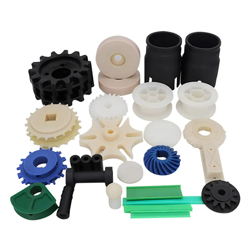
Layout of injection molding cooling water channels
The layout of injection molding cooling channels directly impacts mold cooling efficiency and product quality. A reasonable layout ensures rapid and even cooling of the melt, shortens molding cycles, and reduces the risk of product deformation. Common cooling channel layouts include straight-through, wraparound, branched, spiral, and jet-type. Different layouts are suitable for products of different shapes and structures, and should be flexibly selected based on actual needs.
Straight-through cooling channels are the most basic arrangement, consisting of several parallel straight channels connected by inlets and outlets to form a cooling circuit. This arrangement offers a simple structure and easy processing, making it suitable for flat products with regular shapes and uniform thickness, such as plastic pallets and cover plates. The spacing between straight-through channels is generally 3 to 5 times the product wall thickness, and the diameter is determined by the mold size, typically 8 to 12 mm. To improve cooling uniformity, baffles can be installed at the ends of the channels to ensure that the cooling medium flows fully through the channels, avoiding localized dead water zones. For example, a rectangular plastic plate mold uses four straight-through channels with a diameter of 10 mm, spaced 50 mm apart. Cooling water enters from one side and exits from the other, reducing the product temperature from 200°C to below 60°C within 30 seconds.
Surround cooling channels are suitable for round or curved products, such as plastic cups and barrels. These channels are arranged in a circular pattern, following the contours of the product, ensuring uniform cooling of the curved surface. The radius of the surround channel must match the curvature of the product, generally 5-10mm larger than the contour, to avoid localized overheating or undercooling caused by the close proximity of the channel to the mold cavity. For large round products, multiple rings of surround channels can be used, with spacing of 20-30mm between each ring. These rings can be connected in series or parallel to ensure uniform flow and pressure across the rings. For example, a 300mm diameter plastic barrel mold uses two rings of surround channels: an inner ring with a diameter of 310mm, an outer ring with a diameter of 330mm, and a channel diameter of 12mm. By supplying water in parallel, the cooling rate variation across the barrel is kept within 5%.
The branched cooling water channel consists of a main water channel and several branch water channels. The main water channel is responsible for transporting the cooling medium, and the branch water channels penetrate into the complex structures of the product, such as ribs, bosses, and other parts. This form is suitable for products with complex structures and local thick walls. It can specifically strengthen the cooling of thick-walled areas and reduce shrinkage and deformation. The main diameter of the branched water channel is usually 10~15mm, the branch diameter is 6~8mm, and the branch length should not exceed 50mm, otherwise it will lead to insufficient flow of the cooling medium. For example, a plastic shell mold with multiple ribs has a main water channel diameter of 12mm. Six branch water channels with a diameter of 8mm are set at the corresponding positions of the ribs, which shortens the cooling time of the rib area from the original 45 seconds to 30 seconds, effectively solving the shrinkage problem at the root of the rib.
Spiral cooling channels are often used for deep-cavity products, such as plastic bottles and tubular products. These channels spiral around the core, providing all-around cooling. The pitch of the spiral channel is typically 2-3 times the channel diameter, with a helix angle of 10°-15°. This ensures turbulent flow of the cooling medium within the spiral channel, improving heat transfer efficiency. For ease of processing, the spiral channel can be constructed as a split structure, consisting of two parts, the upper and lower parts. The joints must be sealed to prevent leakage. For example, a 200mm deep plastic bottle mold core utilizes a spiral channel with a diameter of 10mm and a pitch of 25mm. Cooling water enters the core from the bottom, rises along the spiral channel, and exits at the top, rapidly removing heat from the core, ensuring even cooling of the bottle body and maintaining a verticality error within 0.5mm.
Jet cooling channels are suitable for large or extra-thick products, such as automobile bumpers and large plastic housings. Nozzles are installed at the end of the channels to spray the cooling medium directly onto the cavity surface or inside the core, enhancing the local cooling effect. The nozzle diameter of a jet channel ranges from 3 to 5 mm, and the injection pressure is 0.3 to 0.5 MPa. This creates a high-speed jet, destroying the boundary layer on the cavity surface and improving the heat transfer coefficient. For extra-thick products, a jet channel can be installed in the center of the thick wall, allowing inserted nozzles to directly cool the thickest area. For example, a mold for a 50mm thick automobile bumper has four 4mm diameter jet nozzles installed in the thick wall. Cooling water is injected at a pressure of 0.4 MPa, reducing the cooling time of the thick wall from 120 seconds to 80 seconds, significantly improving production efficiency.