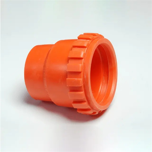
Injection molding valve exhaust (intake)
Injection molding air valves are core control components of the mold’s exhaust and intake systems. By precisely regulating the exhaust and intake of gas, they ensure smooth cavity filling and stable pressure, thereby improving product quality. They not only expel air and volatiles from the mold during the melt filling phase, but also introduce inert gases (such as nitrogen) during the pressure holding phase to compensate for shrinkage. They are widely used in the molding of large, thick-walled parts and complex structures. The exhaust and intake performance of air valves directly impacts mold filling efficiency, part density, and surface quality. Proper selection and commissioning are key to ensuring stable production.
The venting function of an injection molding air valve primarily serves the initial stage of melt filling. A check valve structure within the valve body automatically opens when cavity pressure falls below ambient pressure, exhausting air and gases generated by melt decomposition (such as hydrogen chloride from PVC decomposition). The opening pressure of the vent valve is typically set between 0.01 and 0.05 MPa to ensure the timely discharge of trace gases. It also automatically closes when pressure rises upon the arrival of the melt, preventing melt leakage. The cross-sectional dimensions of the vent channel must match the cavity volume, typically with a diameter of 0.5 to 2 mm and a length of 10 to 30 mm. For high-viscosity plastics (such as PC), the channel diameter can be increased to 1.5 to 2 mm to prevent clogging. For example, a 1 mm diameter vent valve installed in a deep cavity of an automotive door panel mold achieves an exhaust flow rate of 20 ml/s, effectively eliminating air entrapment during filling and reducing the surface scorch defect rate from 15% to 0.3%.
The air intake function is often used in gas-assisted injection molding. The air valve opens when the melt is 70% to 90% filled, introducing high-pressure nitrogen (5 to 30 MPa) into the cavity, pushing the melt to fill the cavity and form a hollow structure, reducing sink marks and warping. The air intake valve’s response time must be ≤ 0.1 seconds to ensure precise gas injection timing and pressure control accuracy of ±0.2 MPa to avoid product dimensional deviations due to pressure fluctuations. The air intake channel must correspond to the thick-walled area of the cavity. For example, air intakes can be set below ribs and bosses to allow gas to form airways preferentially in thick walls. For example, a TV housing mold has an air intake valve installed on the 8mm-thick frame. The nitrogen pressure is 12 MPa, and the holding time is 15 seconds. The product’s sink mark depth is reduced from 0.3mm to 0.05mm.
The valve structure should be selected based on its function. Exhaust valves are categorized into needle valve, ball valve, and diaphragm types. Needle valves offer excellent sealing (leakage ≤ 0.1 ml/min) and are suitable for high-pressure applications. Ball valves offer fast response and are suitable for rapid exhaust. Diaphragm valves are simpler and less expensive, making them suitable for low-pressure, small molds. Inlet valves often use a pilot-operated structure, with a solenoid-controlled valve core opening. They can operate stably under high pressure. For example, the inlet valve used in a 500-ton injection molding machine has an operating pressure range of 5 to 35 MPa and a flow rate adjustment accuracy of ±5%. The connection between the valve and the mold uses a threaded seal (e.g., M10×1.5) with a sealing surface roughness of Ra ≤ 0.8 μm to ensure no gas leakage. The valve should be installed close to the mold cavity, ≤ 50 mm away, to minimize gas transmission losses.
Valve commissioning parameters must be set based on the product structure and material properties. The opening pressure of the exhaust valve must be determined through mold trials. For plastics prone to volatile emissions (such as ABS), the opening pressure can be appropriately reduced to 0.02 MPa to accelerate gas discharge. For plastics with good flowability (such as PE), it should be increased to 0.04 MPa to prevent melt overflow. Inlet valve parameters include injection pressure, hold time, and holding pressure. For thick-walled products (wall thickness ≥ 5 mm), the injection pressure is 15-25 MPa, with a hold time of 10-20 seconds; for thin-walled products (wall thickness ≤ 3 mm), the pressure is 8-15 MPa, with a hold time of 5-10 seconds. For example, a thick-walled PP pipe fitting (wall thickness 10 mm) was molded with 20 MPa of nitrogen injected through the inlet valve and a hold pressure of 18 seconds, reducing the molding cycle from 60 seconds to 45 seconds without causing sink marks.
Air valve maintenance requires regular maintenance. Clean plastic debris and carbon deposits from the exhaust passage weekly using 0.5MPa compressed air or a dedicated needle. Check the valve core for wear monthly. If the wear depth on the sealing surface exceeds 0.05mm, replace the valve core to ensure proper sealing. The intake valve filter should be replaced quarterly to prevent impurities from entering the valve body and causing sticking. For example, a production line experienced intake pressure fluctuations due to a clogged filter. After replacement, pressure stability was restored to ±0.1MPa. Air valves that have been out of service for extended periods require nitrogen maintenance to prevent internal rust and ensure proper operation upon reactivation. Scientifically managing the exhaust and intake functions of air valves can significantly improve mold forming capabilities and improve product quality consistency.