Injection molded exhaust plug exhaust
Injection molding vent plugs are key components of the mold’s exhaust system, used to expel air from the cavity and volatiles released by the plastic melt, preventing defects such as part shortfalls, burning, and weld marks caused by trapped gas. Through precisely designed gaps or pores, vent plugs achieve efficient exhaust without leaking the melt. Widely used in areas difficult to reach by traditional venting slots, such as deep in the cavity and at weld marks, vent plugs are a key means of improving molding quality and production efficiency.

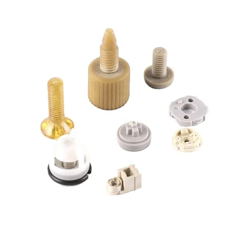
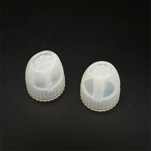
Injection molding vent plugs can be categorized by their venting principle: gap-type, porous-type, and float-valve-type. Gap-type vent plugs consist of a plug body and a gasket, providing venting through an annular gap of 0.01-0.02mm. They are suitable for small and medium-sized molds. The gap size is determined by the plastic viscosity: 0.01mm for low-viscosity plastics (such as PE and PP) and 0.015-0.02mm for high-viscosity plastics (such as PC and POM). For example, a PP mold with a gap-type vent plug installed at the end of the cavity has a 0.01mm gap and a venting rate of 50ml/s, effectively solving the problem of material shortage. Porous-type vent plugs are manufactured using powder metallurgy or laser drilling processes. Their interior is filled with micropores with diameters of 0.01-0.05mm, resulting in a porosity of 30%-50%. This provides a large venting area and is suitable for large and complex molds. For example, an automotive instrument panel mold uses a 10mm-diameter porous vent plug with 0.02mm micropores, achieving 40% higher venting efficiency than gap-type vent plugs.
The installation position of the exhaust plug directly affects the exhaust effect. It needs to be installed in areas where gas is easily retained, such as the area where the cavity is last filled, the intersection of weld marks, and the bottom of deep cavities. For example, for a plastic part with a blind hole, an exhaust plug is installed at the bottom of the blind hole to allow the gas to be discharged directly, avoiding burning; a box-type product has exhaust plugs installed at the four corners to eliminate weld marks at the corners. The distance between the exhaust plug and the cavity should be ≤5mm to ensure that the gas can quickly enter the exhaust channel. The axis of the installation hole must be perpendicular to the cavity surface, with a deviation of no more than 1° to prevent the exhaust channel from tortuosity and affecting the exhaust efficiency. For hot runner molds, an exhaust plug needs to be added near the gate to exhaust the gas in the runner. For example, 3 exhaust plugs are evenly arranged around the point gate with a spacing of 120° to effectively reduce bubbles near the gate.
The dimensions of the vent plug should be determined based on the cavity volume and injection speed. The diameter of the vent plug is typically 5-15mm, and the length is 10-30mm, ensuring adequate venting and structural strength. The formula for calculating exhaust volume is: Exhaust volume = Cavity volume ÷ Filling time × Safety factor (1.2-1.5). For example, if the cavity volume is 50cm³ and the filling time is 2 seconds, the required exhaust volume = 50 ÷ 2 × 1.3 = 32.5cm³/s. Based on this, select a vent plug with an exhaust volume ≥ 35cm³/s. The inlet end of the vent plug should be rounded (R 0.5-1mm) to avoid sharp angles that damage the melt flow. The outlet end should be connected to an exhaust pipe with a diameter of 8-12mm to direct the gas to the outside of the mold. The exhaust pipe should be no longer than 50mm to prevent gas backflow.

The H7/M6 transition fit with the mold plate ensures no melt leakage and facilitates replacement and cleaning. During assembly, apply high-temperature resistant sealant (such as silicone rubber) to the mating surface between the vent plug and the mold plate to enhance the seal. The tightening torque is determined by diameter; for an M8 vent plug, the torque is 15-20 N · m . The vent plug should be cleaned regularly to remove plastic debris trapped in micropores or gaps. Ultrasonic cleaning ( 40 kHz frequency , 10-15 minutes) or compressed air purging ( 0.5-0.6 MPa pressure ) can be used. Cleaning should be done every 3,000-5,000 molds to ensure unobstructed exhaust. For example, a mold experienced product shortages due to a clogged vent plug. After ultrasonic cleaning, the exhaust volume returned to 95% of its initial value, and production resumed normally.

The selection of vent plugs should be based on the plastic’s characteristics and the molding process. For glass-fiber reinforced plastics, wear-resistant carbide vent plugs (such as tungsten carbide) are recommended to prevent gap expansion caused by glass fiber wear. For example, a 30% glass-fiber reinforced PA66 mold using tungsten carbide vent plugs achieved a service life of over 100,000 cycles, while ordinary steel vent plugs leaked after only 30,000 cycles. For high-temperature plastics (such as PEEK, which molds at 380°C), high-temperature vent plugs (with a temperature resistance of ≥400°C) are required to prevent softening and failure. If gas defects are discovered in the product during process adjustments, these can be corrected by increasing the number of vent plugs or increasing the vent gap (without causing overflow). For example, increasing the vent gap from 0.01mm to 0.012mm increases the exhaust volume by 20%, effectively eliminating product scorching. Proper selection and maintenance of vent plugs can significantly improve mold venting capacity, ensuring the production of high-quality products.