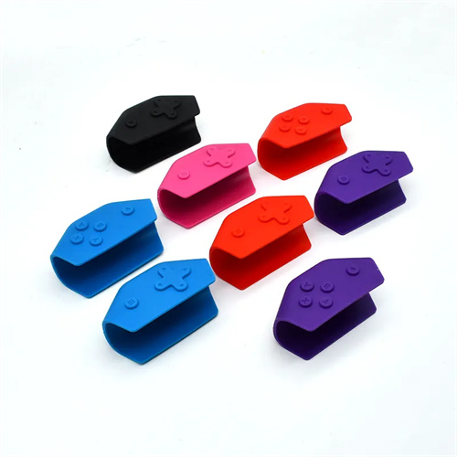
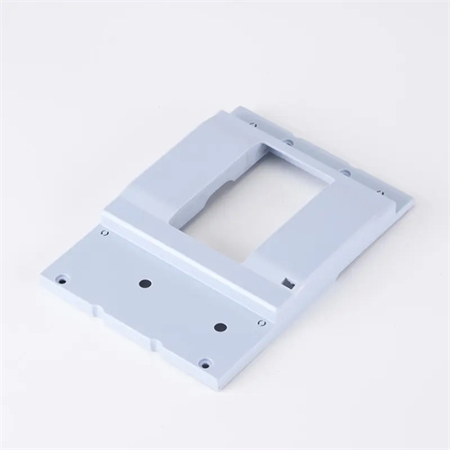
The tilting slider in injection molding is a key component used to create the undercut structure of the molded part. Its parameter calculation directly impacts the smoothness of the core pulling action, molding accuracy, and mold life. The parameters of the tilting slider include the tilt angle, core pulling distance, guide pin length, and locking force. Each parameter must be precisely calculated based on the part’s undercut dimensions, material properties, and mold structure to ensure interference-free and jam-free core pulling while maintaining the dimensional accuracy of the undercut area. Scientific parameter calculation is the core of tilting slider design and the foundation for reliable mold operation.
The tilt angle is the most critical parameter for tilting a slider, directly determining core-pulling efficiency and slider force conditions. It typically ranges from 15° to 25°, with a maximum of 30°. A too small angle will result in insufficient core-pulling distance or excessive slider travel, increasing mold size. A too large angle increases lateral forces on the slider, exacerbating wear on the guide posts and rails, and even causing jamming. The calculation formula is: tilt angle α = arcsin (core-pulling distance S / slider travel L). The core-pulling distance S must be 1-2mm greater than the part’s undercut depth to ensure smooth demolding. For example, if a part has a 5mm undercut depth and a core-pulling distance S of 6mm, and the slider travel L is designed to be 25mm, the tilt angle α = arcsin (6/25) ≈ 13.8°. Adjusting it to 15° means the slider travel L = 6/sin15° ≈ 23.1mm, which satisfies core-pulling requirements while keeping the tilt angle within a reasonable range. For large products, the inclination angle should be smaller (15°~20°) to reduce the weight of the slider and the mold load.
The core-pulling distance must be calculated to cover the full depth of the part’s undercuts and allow for a safety margin. The calculation formula is: S = S1 + S2, where S1 is the part’s undercut depth and S2 is a safety margin (1-3mm). For complex undercuts (such as spiral undercuts or multiple consecutive undercuts), the maximum undercut depth must be calculated as S1 to ensure thorough core pulling. For example, for a part with two undercuts, each 4mm and 6mm deep, S1 is 6mm, S2 is 2mm, and the core-pulling distance S = 8mm. The core-pulling distance must also be aligned with the mold opening distance to ensure the slide can complete the core-pulling motion during the mold opening process. The mold opening distance must be greater than the slide stroke L plus the distance required for other mold movements. When the core-pulling distance is large (e.g., exceeding 30mm), a two-stage core-pulling structure can be used, using a combination of inclined guide columns and hydraulic cylinders to avoid stress issues caused by excessive single tilt angles.
The calculated slider stroke and guide pin length must match each other. Slider stroke L = S/sinα. The guide pin length must be greater than the sum of the slider stroke and the reserved length of the guide pin within the slider. This reserved length is generally 15-20mm to prevent the guide pin from detaching from the slider and causing instability. For example, with a 20° tilt angle and a 10mm core pull distance, the slider stroke L = 10/sin20° ≈ 29.2mm. The guide pin length must be ≥ 29.2 + 20 = 49.2mm, but 50mm is typically used in actual designs. The guide pin diameter is determined by the slider width and is generally 1/5 to 1/4 of the slider width. For example, for an 80mm wide slider, the guide pin diameter should be 16-20mm to ensure sufficient support strength. The clearance between the guide pin and the slider should be H7/h6, and the surface roughness should be Ra ≤ 0.8μm to reduce friction.
Calculating the locking force and locking block parameters requires balancing the lateral force exerted on the slider during injection. Lateral force F = P × A × sinα, where P is the injection pressure (typically 30-50 MPa) and A is the slider molding surface area. The locking force must be 1.2-1.5 times greater than the lateral force to ensure the slider does not retreat during injection. The locking block’s inclination angle should be 1-2° greater than the slider’s to ensure reliable locking. For example, if the slider angle is 20°, the locking block angle should be 21°. The locking block’s contact area must be calculated based on the locking force, ensuring a pressure per unit area of no more than 200 MPa. For a locking force of 50 kN, the contact area must be ≥50,000/200 = 250 mm². The locking block is made of Cr12MoV with a hardness of HRC 58-62 after quenching to ensure wear resistance and strength.
Verifying the strength of an inclined slider is a crucial step in parameter calculation. It’s crucial to verify that the forces acting on the slider, guide post, and inclined guide post are within the material’s allowable range. The formula for verifying the bending strength of the inclined guide post is: σ = M/W ≤ [σ] , where M is the bending moment ( F × L/2 , where F is the lateral force and L is the length of the inclined guide post), W is the cross-sectional modulus (for a circular cross-section, W = πd³/32 , where d is the diameter), and [σ] is the material’s allowable stress ( 150 MPa for quenched and tempered 45 steel ). For example, if the inclined guide post has a diameter of 12mm and a length of 100mm , and the lateral force is 10kN , M = 10000 × 0.1/2 = 500N · m , W = π × 0.012³/32 ≈ 1.7 × 10⁻⁸m³ , and σ = 500/1.7 × 10⁻⁸ ≈ 29.4 MPa ≤ 150MPa, meeting the strength requirements. Slider rail pressure verification must ensure a pressure of ≤ 15MPa to prevent excessive wear. For large sliders, the rail width can be increased or rolling guides can be used to reduce friction. Comprehensive parameter calculation and strength verification are essential to ensure the long-term stability and reliability of inclined sliders.