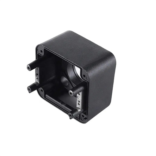
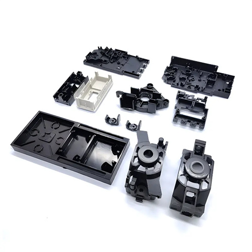
Injection molding machine adjustment skills: positioning injection method
Positioned injection is an advanced technique for precisely controlling the melt filling process during injection molding machine setup. Its core principle is to precisely control the melt filling volume and speed by presetting the screw at a specific position within the barrel as the injection endpoint, thereby improving the dimensional accuracy and weight stability of the plastic part. Compared with traditional time-controlled injection, the positioned injection method can more directly reflect the filling state of the melt within the mold cavity, reducing the impact of factors such as raw material property fluctuations and equipment wear on the filling process. For example, in the production of precision plastic parts (such as electronic connectors), the positioned injection method can control the weight error of the plastic part to within ±0.5%, far exceeding the ±2% of traditional methods, significantly improving product consistency.
The key to the targeted injection method lies in properly setting the injection endpoint. This position requires a comprehensive calculation based on factors such as the part’s volume, gate size, and melt fluidity. First, the part’s volume is calculated based on a 3D model, taking into account melt volume loss in the runners and gates to determine the required injection volume. Next, the screw displacement corresponding to this injection volume is calculated based on the injection molding machine’s screw diameter and pitch, representing the injection endpoint. For example, for a part with a volume of 50 cm³, if the runner and gate volumes are 5 cm³, the total injection volume is 55 cm³, and each centimeter of screw displacement corresponds to an injection volume of 10 cm³, the injection endpoint should be set at 5.5 cm of screw advance. Furthermore, the compressibility of the melt must be considered. For crystalline plastics (such as polyethylene and polypropylene), due to their high melt compressibility, the injection endpoint typically needs to be positioned 0.1-0.3 cm ahead of the theoretically calculated value to compensate for volume shrinkage during cooling.
During machine setup for the fixed-point injection method, the screw injection speed and pressure must be adjusted in stages to accommodate the melt flow requirements during the various filling phases. The injection process is typically divided into three phases: low-speed filling, high-speed filling, and deceleration before holding pressure, each corresponding to a different screw position range. The low-speed filling phase (typically from the injection start to 20% of the total stroke) primarily prevents melt jetting at the gate, preventing silver streaks or scorch marks on the part surface. The high-speed filling phase (20%-80% of the total stroke) aims to quickly fill the cavity, minimizing melt cooling during the filling process and is suitable for thin-walled or complex parts. The deceleration phase (80%-100% of the total stroke) reduces the injection speed to ensure a smooth transition from the melt to the holding phase, preventing overfilling due to inertia. For example, when producing thin-walled parts with a thickness of 1mm, the speed during the high-speed filling phase can be set to 80-100mm/s, while the speed during the deceleration phase before holding pressure is reduced to 20-30mm/s.
The positioning injection method places high demands on the hardware performance and control system accuracy of the injection molding machine. The screw position detection accuracy, injection speed stability, and pressure control response speed all affect the machine adjustment effect. Screw position detection usually uses a high-precision grating ruler or encoder with a resolution of no less than 0.01mm to ensure the control accuracy of the injection endpoint position. The stability of the injection speed requires that the speed fluctuation does not exceed ±2% under different loads to avoid unstable melt flow in the mold cavity due to sudden speed changes, resulting in bubbles or weld marks. The response speed of the pressure control needs to be within 50ms to ensure that the holding pressure can be quickly switched to when the injection endpoint is reached to prevent overfilling. For example, injection molding machines driven by servo motors perform better in the positioning injection method, with their position control accuracy and speed stability far exceeding those of traditional hydraulically driven injection molding machines.
In practice, machine tuning for the fixed-point injection method requires multiple mold trials and parameter optimization to achieve optimal results. Initially, a preliminary mold trial is conducted to observe the filling of the part. If material shortages occur, the injection endpoint can be appropriately moved back (increasing the injection volume); if flash is present, the endpoint can be moved forward (reducing the injection volume). The injection speed and pressure at each stage are then adjusted based on part weight fluctuations to ensure that the part weight remains within the specified range. Furthermore, fine-tuning of parameters is necessary based on the part’s appearance. If weld marks are observed on the surface, the speed of the high-speed filling stage can be increased or the stroke length can be extended. If burnt marks are present on the surface, the speed of the low-speed filling stage can be reduced or the stroke length can be shortened. For example, in the production of a mobile phone casing, by extending the stroke length of the high-speed filling stage from 60% to 70% of the total stroke and increasing the speed by 10%, weld marks on the side of the part were successfully eliminated while maintaining a weight tolerance within ±0.3%. With the development of intelligent injection molding technology, the positioning injection method has been combined with the adaptive control algorithm, which can automatically adjust the injection end point position and parameters of each stage according to the real-time monitored plastic part quality data, further improving the machine adjustment efficiency and production stability.