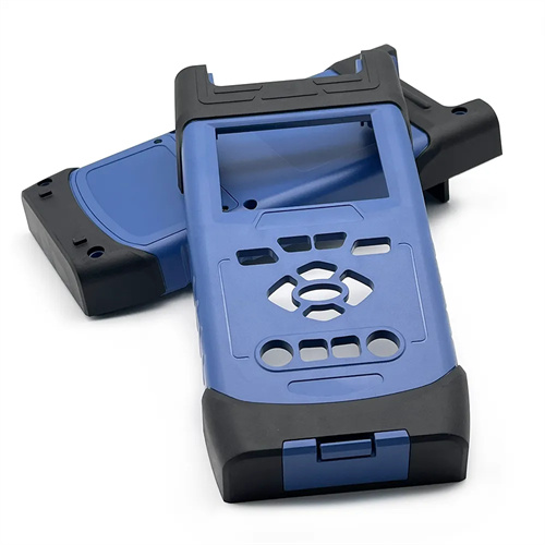
Injection molded push block design
Injection molding ejector blocks are block-shaped ejection components used to demold large or irregularly shaped plastic parts. They feature a large contact area with the part and uniform ejection force, effectively preventing deformation or cracking during ejection of thin-walled parts or brittle plastics (such as PS and PMMA). The ejector block design is customized to the part’s contours, typically conforming to a portion or the entire surface. It is suitable for large parts such as automotive dashboards and appliance housings. For example, in a PMMA automotive lampshade mold, the alignment error between the ejector block and the lampshade’s curved surface must be less than 0.05mm to ensure uniform force during ejection and prevent stress marks on the optical surface.
The pusher block’s structural form should be selected based on the molding location of the plastic part. Integral pusher blocks are suitable for large, regular-shaped plastic parts, such as flat parts. These blocks are typically 5-10mm larger than the part’s outer contour and 15-30mm thick. They are made of quenched and tempered 45-gauge steel (HRC 28-32), with a surface-milled cavity that matches the part. Modular pusher blocks are used for complex, irregularly shaped parts. They are assembled from multiple sub-blocks, with a 0.05-0.1mm gap between each block to prevent movement interference. For parts with bosses or ribs, the pusher block requires a clearance groove 1-2mm deeper than the boss height, with a 0.5mm gap on each side. For example, a mold for a washing machine control panel utilizes a modular pusher block consisting of three sub-blocks, corresponding to the panel’s key area, display area, and edge. Dowel pins precisely align the sub-blocks, ensuring a flatness tolerance of ≤0.3mm after ejection.
The design of the pusher block’s guidance and positioning structure is crucial for ensuring precise movement. The pusher block requires four to six sets of guide pins and bushings. The guide pins have a diameter of 16-25 mm and are located at the four corners of the block. The guide bushing length should be ≥ 1.5 times the guide pin diameter, with a clearance of 0.02-0.04 mm. The pusher block is secured to the push plate with countersunk bolts, with one bolt required for every 100 cm² of the block area. A positioning key (10-15 mm wide and 5-8 mm high) is also required at the bottom of the block to prevent displacement during movement. For example, in a large automobile bumper mold, the pusher block measures 1200 mm x 600 mm and is guided by eight φ20 mm guide pins, secured by six M16 bolts, and secured with four positioning keys. The parallelism error is controlled within 0.03 mm/m.
The material and surface treatment of the pusher block must balance strength and mold release performance. Small pusher blocks (area <500 cm²) are constructed of 45-gauge steel with a chrome plating thickness of 5-10 μm for improved wear resistance. Large pusher blocks are constructed of welded Q235 steel with internal reinforcement ribs (spaced 100-150 mm apart) to prevent deformation. The working surface is hardened with 5 mm thick H13 hot-work die steel, achieving a hardness of HRC 45-50 after quenching. The surface roughness of the pusher block contacting the plastic part must be Ra ≤ 0.8 μm. For high-gloss plastic parts (such as piano-finish finish housings), the surface must be polished to Ra ≤ 0.02 μm to avoid ejection marks. For example, the working surface of the pusher block in a high-end refrigerator door panel mold is ultra-polished and, in combination with a release agent, achieves a 90° glossiness (measured at a 60° angle) after ejection, meeting Class A surface requirements.
The ejection parameters of the ejector block must be designed to match the material properties of the plastic part. For brittle plastics, the ejection speed should be controlled at 5-10 mm/s to prevent cracking caused by excessive impact. For tough plastics (such as PP and PE), this can be increased to 15-20 mm/s to improve production efficiency. The ejector block’s ejection stroke should be 5-10 mm greater than the part’s height to ensure complete release from the mold cavity. When the clamping force between the part and the cavity is high, auxiliary ejector pins (3-5 mm in diameter) should be installed on the ejector block, distributed along the block’s edges or in weak areas to aid demolding. For example, when producing glass fiber reinforced PP automotive door panels, the ejector block’s ejection stroke is set at 30 mm. Combined with eight auxiliary ejector pins, the ejection force is reduced from 5000 N for a simple ejector block to 3500 N without deforming the door panel. Furthermore, the ejector block should be equipped with a return limiter (such as a stopper post) to ensure that the clearance with the cavity plate is ≤ 0.02 mm after reset to prevent crushing during mold closing.