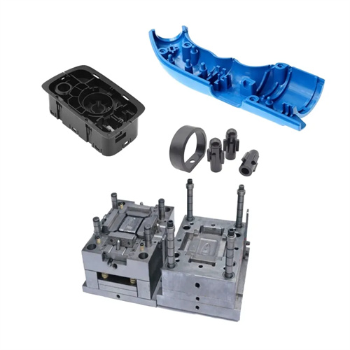
Injection mold cavity arrangement
Injection molding cavity arrangement is a key step in mold design that determines production efficiency and plastic part quality. It refers to the reasonable arrangement of the position and number of multiple cavities on the movable and fixed mold plates to achieve the purpose of injection molding multiple plastic parts at one time. The rationality of cavity arrangement directly affects the structural stability of the mold, the dimensional consistency of the plastic parts, and the economic efficiency of production. In mass production, scientific cavity arrangement can significantly improve production efficiency and reduce the manufacturing cost per unit product; while unreasonable arrangement may lead to uneven filling of plastic parts, inconsistent cooling, and even cause problems such as mold overload deformation. Therefore, cavity arrangement design needs to comprehensively consider multiple factors such as plastic part structure, injection molding machine parameters, production requirements, etc., and is an indispensable and important step in mold design.
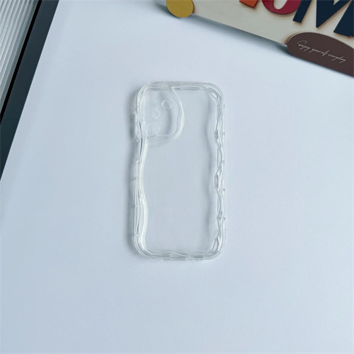
Determining the number of cavities is the basis for cavity placement and requires a comprehensive calculation based on the injection molding machine’s rated clamping force, shot size, and the size and weight of the part. First, based on the machine’s maximum shot size, the number of cavities should ensure that the single shot volume does not exceed 70%-80% of the machine’s rated shot size. This ensures sufficient space for the melt to compress and avoid defects such as underfill and flash. For example, if the machine’s rated shot size is 500g and the part weight is 50g, the theoretical number of cavities can be initially set at 8 (500 x 80% ÷ 50 = 8). Secondly, the clamping force must be calculated to ensure it meets the requirements. Using the formula F = P x A (where F is the clamping force, P is the average cavity pressure, and A is the projected area of the part on the parting surface), ensure that the calculated clamping force is less than the machine’s rated clamping force. In addition, the production batch of plastic parts also needs to be considered. For large-scale production, the number of cavities can be appropriately increased to improve efficiency; while for precision plastic parts or trial production stages, a single cavity or a small number of cavities are usually used to ensure quality stability.
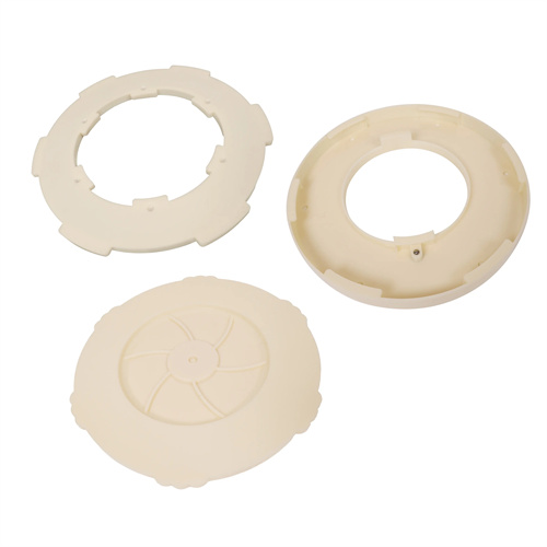
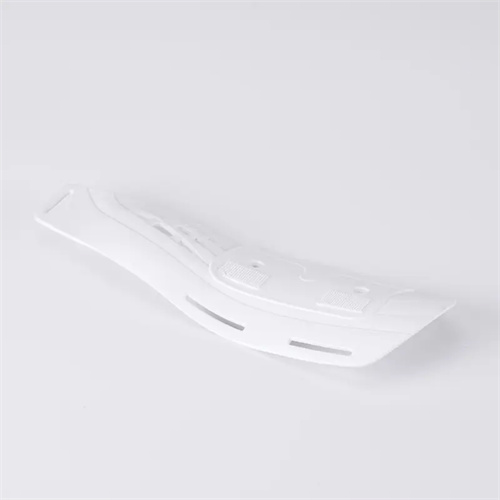
The cavity layout must adhere to the principles of symmetry and balance to ensure consistent melt filling speed and pressure distribution within each cavity. Common arrangements include circular, rectangular, and linear. The circular arrangement is suitable for small and medium-sized plastic parts. The cavities are radially distributed around the sprue, with each cavity equidistant from the sprue. This effectively ensures uniform filling and is commonly used for parts such as bottle caps and small gears. The rectangular arrangement is suitable for larger parts. The cavities are neatly arranged in rows and columns, facilitating mold processing and cooling system layout. This arrangement is commonly used for parts such as automotive interiors and appliance housings. The linear arrangement is often used for long, rectangular parts. The cavities are arranged along a straight line, simplifying the design of the mold’s feed system. Regardless of the arrangement, central symmetry of the cavities is crucial to ensure balanced forces during the injection molding process and avoid mold plate deformation or guide pin wear due to uneven loading.
The relative positioning of the cavity, main runner, and branch runner directly impacts the melt’s flow path and filling efficiency. The main runner should be located as close to the center of the mold as possible, ensuring that the distances from the branch runner to each cavity are equal or close, minimizing pressure loss and temperature variations during melt flow. For multi-cavity molds, the length and cross-sectional dimensions of the branch runners must be appropriately designed based on the cavity location. For cavities close to the main runner, the branch runners can be appropriately reduced in size, while those further away from the main runner should be increased to balance the filling speeds of each cavity. Furthermore, the location and form of the gate must be coordinated with the cavity layout design. For symmetrically arranged cavities, the gate should be located at the center of the part or at the same location to ensure consistent molding conditions for each part. For example, for rectangular cavities, side gates can be symmetrically distributed on the same side of the part, ensuring that the melt enters each cavity at the same angle and speed, avoiding dimensional deviations caused by differences in filling times.
The mold’s cooling system and structural strength must also be considered when arranging cavities. When arranging cavities, sufficient space must be reserved for cooling channels to ensure even cooling of each cavity, preventing differential shrinkage or warping of the plastic part due to uneven cooling. Cooling channels should be symmetrically distributed around the cavity, typically with a channel diameter of 8-12 mm and a distance of 15-25 mm from the cavity surface to ensure a balance between cooling efficiency and mold strength. Furthermore, sufficient wall thickness between cavities—generally no less than 10-15 mm—must be maintained to ensure sufficient mold rigidity and prevent deformation or cracking under clamping forces. For large or multi-cavity molds, reinforcing ribs should be installed around the cavities to enhance the mold’s resistance to bending. Furthermore, the cavity layout should facilitate mold processing and maintenance. Cavities should be positioned away from mold guide pins, guide bushings, and other components to minimize machining interference, while also allowing ample operating space for later repairs and maintenance.