Secondary demoulding is used in injection molding due to excessive clamping force
During the injection molding process, when the clamping force exerted by the plastic part on the core or cavity is excessive, using a single demolding operation often results in deformation, cracking, or surface damage to the part, or even makes it impossible to remove from the mold. Excessive clamping force often occurs in parts with deep cavities, thin walls, complex curves, or undercut structures. Because the part cools and shrinks, it exerts a strong clamping force on the core. The ejection force during a single demolding operation is concentrated on a localized area of the part, potentially causing damage. To address this issue, a secondary demolding mechanism has been developed. Through two distinct demolding actions, the clamping force on the part is gradually reduced, allowing the part to be released smoothly and safely from the mold, thereby ensuring part quality and integrity. The core design of a secondary demolding mechanism, employed due to excessive clamping force, lies in the rational distribution of force and stroke during the two demolding operations, ensuring a gradual release of the clamping force and preventing excessive stress on the part.
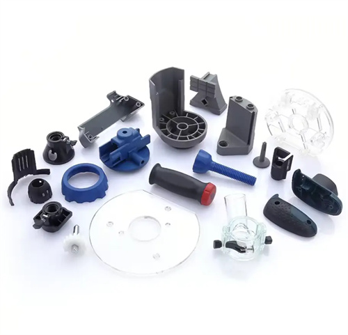
Deep-cavity plastic parts often require a secondary demolding process due to high clamping forces. For example, a plastic water cup mold, 150mm tall and 2mm thick, is made of PP and features spiral reinforcement ribs on the inner surface. This creates a significant clamping force on the core after molding. With a single demolding process, the ejector pin directly pushes against the cup’s base. Because the clamping force is concentrated on the core surface, the part is prone to circumferential cracking or axial tensile deformation during ejection, resulting in scrap rates exceeding 30%. Analysis reveals that the primary cause of this is that the ejection force acts instantaneously on the bottom of the part during single demolding, resulting in high friction (clamping force) between the part and the core, causing localized forces on the part to exceed the material’s yield strength. To address this issue, a secondary demolding mechanism with an inclined wedge and slider was designed. During the first demolding step, the inclined wedge drives the slider, driving the annular ejector sleeve to lift the part 50 mm from the core, reducing the contact area between the part and the core by about one-third and initially releasing some of the clamping force. During the second demolding step, the ejector pin pushes against the bottom of the cup, completely ejecting the part from the annular ejector sleeve. Through these two demolding steps, the clamping force on the part is gradually released, the ejection force is more evenly distributed, and the scrap rate is reduced to below 1%.
Thin-walled plastic parts, due to their thin walls and poor rigidity, are more susceptible to deformation during primary demolding when excessive clamping forces are applied. Secondary demolding effectively protects the part’s shape accuracy. For example, a mobile phone housing, with a wall thickness of only 1.2mm and made of ABS, contains multiple internal bosses and ribs for mounting components, exerting a significant clamping force on the core after molding. During primary demolding, ejector pins push against the edges of the housing. Due to the part’s insufficient rigidity, the housing is prone to localized dents or warping during ejection, affecting assembly accuracy. To address this issue, a tie-rod secondary demolding mechanism was implemented. During the first demolding, after the movable and fixed molds separate a certain distance, the tie-rod drives the primary ejector plate to push against the ejector plate, lifting the part 3-5mm from the cavity, separating it from the inner wall and releasing the clamping force on the part’s outer surface. During the second demolding, the ejector plate drives the ejector pins to eject the part from the core, completing the entire demolding process. Since the clamping force between the plastic part and the cavity is released during the first demolding, the plastic part is only subjected to the friction between the plastic part and the core during the second demolding. The ejection force is smaller and more evenly distributed, effectively avoiding deformation of the plastic part and ensuring the flatness and dimensional accuracy of the shell.
For plastic parts with undercuts or complex curved surfaces, the clamping force comes not only from the shrinkage-generated clamping force but also from the mechanical locking of the undercut structure. Secondary demolding can be performed by first releasing the undercut lock before the entire part is demolded. For example, a plastic part for an automotive air conditioner vent blade has rotating shaft holes at each end, with annular undercuts within the holes for axial positioning during assembly. After molding, the combined mechanical locking force of the undercuts and the core, combined with the shrinkage-generated clamping force, results in extremely high clamping forces. During primary demolding, ejection from either direction can easily cause the part to tear at the undercut or deform the shaft hole. To address this, a rocker-type secondary demolding mechanism was designed. During the first demolding, a rocker, under the action of a spring, drives a slider to remove the undercut core from the shaft hole, releasing the mechanical locking force. Now, the part is in contact with the main core solely through shrinkage-generated clamping. During the second demolding, an ejector pushes against the blade end, ejecting the part from the main core. The secondary demolding method of first removing the undercut core and then ejecting the plastic part effectively decomposes the clamping force, avoids damage to the plastic part at the undercut, and ensures the dimensional accuracy and assembly performance of the shaft hole.
The design of the secondary demolding mechanism requires careful consideration of the structural characteristics of the part and the distribution of clamping forces. The mechanism type must be appropriately selected, and the stroke and force distribution for both demolding cycles must be determined. For parts where the clamping force is primarily distributed on the core surface (such as deep-cavity parts), the initial demolding stroke should reduce the contact area between the part and the core by 1/3-1/2 to significantly reduce the clamping force. The secondary demolding stroke must ensure smooth part removal. For thin-walled parts with poor rigidity, the initial demolding force should be distributed as evenly as possible across the part surface (e.g., using a demolding plate) to avoid excessive localized force. For the secondary demolding, ejector pins or ejector plates can be used, and the ejection force should be controlled within the material’s allowable range. For parts with undercuts, the primary demolding step is to release the mechanical lock of the undercuts, and the stroke must ensure complete separation of the undercuts from the core. Conventional ejection methods can be used for the secondary demolding. Furthermore, the sequence and coordination of the secondary demolding mechanism are crucial. Limiters, springs, and hydraulic or pneumatic components must be used to precisely control the timing and travel of the two demolding operations to avoid interference or incomplete demolding. Furthermore, the strength and wear resistance of the mechanism must be fully considered to ensure stable operation over long-term production, thereby improving production efficiency and product quality.