Injection mold tolerances and fits
The tolerances and fits of injection molds are crucial technical indicators for ensuring the precise assembly and performance of mold components. They directly impact the mold’s service life, the dimensional accuracy of the plastic part, and the stability of the molding process. Mold tolerance refers to the allowable variation between the actual and designed dimensions of mold components, while fit refers to the clearance or interference fit between two assembled parts. Properly determining mold tolerances and fits ensures smooth movement and accurate positioning between mold components, preventing loosening, sticking, and leakage. This reduces mold wear and extends its service life. The selection of mold tolerances and fits requires a comprehensive consideration of factors such as the mold’s operating conditions, the function of the components, the processing technology, and economic feasibility, adhering to the principle of “meeting application requirements while reducing manufacturing costs.”
The tolerance grade of mold components should be differentiated based on their function and precision requirements. Working parts (such as the cavity, core, and sprue bushing) directly contact the plastic melt and determine the dimensional accuracy of the part. These components have higher tolerance requirements, typically IT5-IT7. For example, the dimensional tolerances of the cavity and core should be determined based on the tolerance grade of the part, generally 1-2 grades higher to ensure the part meets the required dimensional accuracy. Guide and positioning components (such as guide pins, guide bushings, and locating pins) must ensure precise mold opening and closing movements. Tolerance grades of IT6-IT8 are typically selected, and clearances and interference fits must be strictly controlled to avoid compromising guiding accuracy due to improper fit. Structural components (such as mold plates, backing plates, and screws) primarily serve support and connection functions. These components have relatively low tolerance requirements, typically IT9-IT12, to reduce processing costs. In addition, the tolerance grade of mold parts should also match the processing technology. For example, grinding can reach IT5-IT6 level, and milling can reach IT8-IT9 level. The tolerance grade should be reasonably determined according to the processing method of the parts.
Mold component fits primarily include clearance fit, transition fit, and interference fit, each suited to different operating scenarios. A clearance fit occurs when the actual hole dimensions are larger than the actual shaft dimensions, resulting in a certain amount of clearance after assembly. This fit is suitable for parts requiring relative motion, such as guide pins and guide sleeves, or push rods and platens. The size of this clearance should be determined based on the parts’ motion speed, operating temperature, and lubrication conditions. For example, the clearance between guide pins and guide sleeves is typically 0.01-0.03mm, ensuring both flexible movement and guiding accuracy. A transition fit occurs when the actual hole dimensions may have clearance or interference, but the amount of this clearance or interference is minimal. This fit is suitable for parts requiring precise positioning and infrequent disassembly, such as the fit between locating pins and locating holes, or the fit between a sprue bushing and a fixed platen. A transition fit ensures precise positioning between parts while facilitating assembly and disassembly. An interference fit occurs when the actual hole dimensions are smaller than the actual shaft dimensions, resulting in a certain amount of interference after assembly. This fit is suitable for parts requiring a secure connection, such as the fit between a gear and shaft, or between an insert and a platen. The size of the interference should be determined according to the connection strength requirements. Too large an interference will cause deformation of parts or difficulty in assembly, while too small an interference cannot guarantee the firmness of the connection.
The geometric tolerances (form and position tolerances) of mold components also have a significant impact on mold accuracy and need to be controlled in conjunction with dimensional tolerances. Geometric tolerances include straightness, flatness, roundness, cylindricity, parallelism, perpendicularity, and coaxiality, and are used to limit errors in the shape and position of parts. For example, the working surfaces of the cavity and core must be controlled for flatness or roundness to ensure the surface quality of the molded part; the axes of guide pins and guide bushings must be controlled for straightness and coaxiality to ensure smooth movement of the guide mechanism; and the mounting surfaces of the mold plate must be controlled for flatness and parallelism to ensure overall accuracy after mold assembly. Geometric tolerance grades typically match dimensional tolerance grades. For example, a part with an IT6 dimensional tolerance can have a geometric tolerance of grades 6-7 to avoid excessive geometric errors that could affect part fit. When marking geometric tolerances, the datum should be appropriately selected based on the functional requirements of the part to ensure that the tolerance requirements are clearly targeted and measurable.
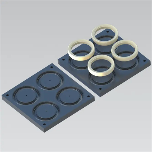
The design of mold tolerances and fits also needs to consider the shrinkage rate of the plastic and the impact of the molding process to ensure that the plastic part achieves the designed dimensional accuracy. After molding, plastic shrinks due to factors such as temperature drop and molecular orientation. Different plastics have different shrinkage rates, and the shrinkage rate of the same plastic can also vary under different molding conditions. Therefore, the dimensions of the mold cavity and core must be calculated based on the nominal dimensions and shrinkage rate of the plastic part, while also allowing for appropriate tolerances to compensate for shrinkage fluctuations. For example, for a polyethylene part with a shrinkage rate of 0.5%-2%, the mold cavity dimensional tolerance should be 1.5-2 times larger than the part dimensional tolerance to ensure that the part meets the required dimensions after molding. Furthermore, molding process parameters such as temperature, pressure, and dwell time can also affect the dimensional accuracy of the plastic part. Therefore, the design of mold tolerances and fits should be adaptable and able to compensate for fluctuations in process parameters within a certain range. In short, the design of mold tolerance and fit is a comprehensive technical work that needs to combine multiple factors such as part function, processing technology, material properties and molding requirements. By reasonably selecting tolerance grades and fit types, the assembly accuracy and working performance of the mold can be ensured, and ultimately the stable production of high-quality plastic parts can be achieved.