Two important reasons why air entrapment is easy to occur during injection molding
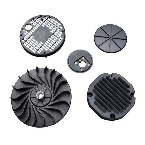
During the injection molding process, air entrapment is a common problem that causes defects such as burning, material shortage, and bubbles in the products, which seriously affects product quality and production efficiency. Among them, the unreasonable design of the mold exhaust structure is one of the important reasons for air entrapment. If there is a lack of effective exhaust channels inside the mold cavity, or the position and size of the exhaust groove are improperly set, the plastic melt will not be able to discharge the air in the cavity in time during the filling process. When the melt fills the cavity at a high speed, the air is compressed in a small space. As the pressure continues to rise, the air temperature rises sharply, which may exceed the thermal decomposition temperature of the plastic, and then cause burn marks to appear on the surface of the product. For example, when molding plastic parts with complex structures, such as parts with deep cavities, narrow gaps or thin walls, air is very easy to accumulate here. If the exhaust groove is not set accordingly here
In some areas, air entrapment problems will frequently occur. In addition, if the depth and width of the venting groove do not meet the requirements, being too shallow will lead to poor venting, while being too deep may cause flash, which places high demands on the experience and technology of the mold designer.
A mismatch between the plastic melt’s fluidity and the filling speed is another key factor contributing to air entrapment. When the plastic melt has poor fluidity and the injection molding machine’s fill speed is set too high, the melt’s flow within the mold cavity becomes turbulent, preventing the orderly removal of air from the venting area. A poorly fluid melt struggles to quickly fill every corner of the cavity, forming an irregular “front” at the flow front, which can easily trap air within the melt, forming bubbles or air pockets. Conversely, if the melt has excessive fluidity but the filling speed is too slow, the melt may cool and solidify before reaching the end of the cavity, similarly trapping air in the unfilled space. For example, when processing relatively poorly fluid materials like polycarbonate, if the filling speed is not adjusted according to the material’s properties, air can easily be trapped in dead corners of the part. Furthermore, the melt and mold temperature settings can also affect fluidity. Excessively low temperatures reduce melt fluidity, indirectly exacerbating air entrapment. This requires precise control by the operator during production.
The structural complexity of the mold cavity will also indirectly amplify the impact of the above two reasons. For molds with complex surfaces, multiple inserts or slender holes, the air flow path inside the cavity is already tortuous. If the exhaust design and melt filling parameters fail to adapt to this structure, the air entrapment problem will be more prominent. For example, when molding a plastic part with multiple reinforcing ribs, the narrow space between the reinforcing ribs can easily become a “dead corner” for air accumulation. At this time, if the exhaust grooves do not extend to these areas, or the melt filling speed is not adjusted in sections according to the distribution of the ribs, it will cause the roots of the ribs to burn or lack material. In addition, if there is an uneven fit clearance on the parting surface of the mold, it will also affect the air exhaust efficiency, further increasing the risk of air entrapment.
The dryness and melt state of the raw materials also have an indirect impact on the problem of air entrapment. If the plastic raw materials contain excessive moisture or volatiles, a large amount of gas will be generated during the high-temperature melting process. These gases mix with the air in the mold cavity, increasing the burden on the exhaust system and exacerbating air entrapment. For example, if highly hygroscopic plastics such as polyamide (PA) are not dried sufficiently, the water vapor generated during melting will form bubbles in the mold cavity, affecting the fluidity of the melt and making exhaust during the filling process more difficult. In addition, the uneven plasticization of the melt in the barrel and the presence of incompletely melted particles will lead to unstable melt flow, which in turn disrupts the air exhaust path and increases the possibility of air entrapment. Therefore, strict control of the drying process and melting quality of the raw materials is an important auxiliary measure to reduce the problem of air entrapment.
Improper adjustment of process parameters during production can also lead to frequent, avoidable air entrapment. In addition to filling speed, the settings of parameters such as injection pressure, holding time, and melt temperature are closely related to air entrapment. If the injection pressure is too high, the melt fills too quickly, preventing air from escaping quickly. If the pressure is too low, the melt may not fully fill the mold cavity, similarly leaving space for air to linger. Holding times that are too long or too short can also affect the melt’s shrinkage compensation, which in turn affects the escape of internal gas. For example, when molding thick-walled plastic parts, insufficient holding time can cause vacuum bubbles to form inside the melt as it cools and shrinks. These bubbles, while seemingly bubbles, are caused by a different mechanism than air entrapment, but can also be mistaken for air entrapment. Therefore, operators need to precisely optimize various process parameters based on the part structure, raw material properties, and mold design to minimize the occurrence of air entrapment.