Injection pressure is the key dynamic parameter that propels the plastic melt into the mold cavity during the injection molding process, directly affecting the melt’s flow properties, filling speed, and the compactness of the plastic part. Its value must be determined based on a comprehensive consideration of factors such as the plastic’s properties, the part’s structure, and the mold design. Excessively high or low injection pressure can lead to product quality defects. For example, insufficient pressure can result in incomplete cavity filling, leading to problems such as material shortages and sink marks. Excessive pressure can increase internal stress in the plastic part, causing cracking and flash, while also increasing mold wear and equipment energy consumption. Therefore, precise control of injection pressure is crucial for ensuring stable injection molding production and product quality, requiring systematic management from multiple perspectives, including theoretical calculation, parameter setting, and dynamic adjustment.
Theoretical calculations of injection pressure must be based on melt flow resistance, taking into account factors such as the part’s flow length ratio, wall thickness, and mold runner structure. The flow length ratio (the ratio of the part’s maximum flow distance to its average wall thickness) is a key indicator of injection pressure. A larger flow length ratio increases the pressure loss during melt flow and, consequently, the required injection pressure. For example, for a thin-walled part with a flow length ratio of 150, the required injection pressure may reach 150-180 MPa; whereas, for a thick-walled part with a flow length ratio of 50, the injection pressure can be controlled within 80-100 MPa. Pressure loss in the mold runners is also important. The cross-sectional dimensions, length, and roughness of the main runners, branch runners, and gates all affect melt flow resistance. Smaller runner cross-sections and longer runner lengths increase the required injection pressure. Therefore, during the design phase, CAE simulation software should be used to calculate the pressure distribution during melt flow to initially determine a reasonable injection pressure range, providing a reference for subsequent mold trials.
Plastic properties significantly influence the choice of injection pressure. Different plastics have varying melt viscosities and fluidity requirements, requiring different injection pressures. High-flow plastics (such as PE and PP) have low melt viscosity and minimal flow resistance, requiring lower injection pressures, typically 50-100 MPa, to meet filling requirements. For example, when molding thin-walled PP containers, the injection pressure is typically set at 70-80 MPa, ensuring rapid filling while avoiding flash. Low-flow plastics (such as PC and POM) have high melt viscosity and require higher injection pressures to overcome flow resistance, typically in the 100-180 MPa range. For example, in PC lenses, due to their high melt viscosity and temperature sensitivity, injection pressures of 120-150 MPa are required, coupled with a relatively high barrel temperature (300-320°C) to ensure the melt fully fills the fine structures of the cavity. In addition, the elastic modulus of the plastic will also affect the injection pressure. Plastics with high elastic modulus (such as ABS) require higher holding pressure in the later stage of filling to compensate for shrinkage. Therefore, the setting of the injection pressure must reserve sufficient holding pressure margin.
Part structure and mold design are key factors in determining the actual injection pressure requirements. Complex structures and precise dimensions require higher injection pressure control precision. Parts with elongated holes, deep cavities, or intricate patterns present greater flow resistance to the melt during filling, necessitating higher injection pressures. For example, when molding parts with multiple pores less than 2mm in diameter, injection pressure must be increased by 20%-30% compared to standard parts to ensure the melt can fill the tiny pores. Mold venting performance also affects injection pressure. Poor venting can compress air in the cavity, creating back pressure. In this case, higher injection pressure is required to overcome this back pressure and complete filling. However, excessive back pressure can cause melt degradation or burn the part. Therefore, the mold should be equipped with sufficient venting grooves ( 0.02-0.05mm in depth) to minimize injection pressure increases caused by venting issues. Furthermore, the location and shape of the gate also influence pressure distribution. Point gates, due to their smaller cross-section, generate greater pressure loss and require 10%-15% higher injection pressure than side gates.
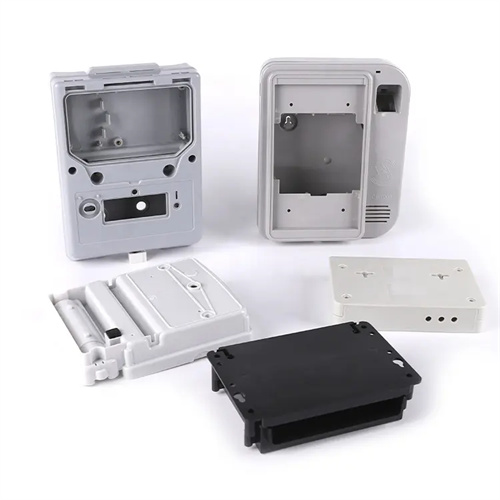
Staged injection pressure control is an effective means of optimizing the filling process and improving product quality. By dividing the injection process into multiple stages and setting different pressure parameters, smooth melt filling is achieved. A lower pressure (50%-70% of maximum pressure) can be used in the initial stage (filling the runners) to avoid excessive shearing of the melt within the runners. As the melt approaches the cavity, the pressure is increased to 80%-90% to ensure rapid cavity filling and reduce cooling time. When the cavity is 90%-95% full, the pressure is reduced to 30%-50% to prevent flash and overfilling. For example, when molding ABS housing parts, pressure control can be divided into three stages: 80 MPa in the first stage (runner filling), 120 MPa in the second stage (main cavity filling), and 60 MPa in the third stage (end filling). This step-by-step pressure adjustment ensures that the melt flow state at each stage matches the cavity structure. The switching points for the staged pressures are determined based on the cavity filling level and can be monitored in real time by the injection molding machine’s position or pressure sensors to ensure precise switching timing.
Matching injection pressure with other process parameters is crucial to product quality. Injection speed, temperature, and holding pressure, among other parameters, must be coordinated and controlled to achieve the optimal process combination. Matching injection pressure and injection speed is crucial. High-speed injection creates greater kinetic energy in the melt, so injection pressure can be appropriately reduced. Low-speed injection requires increased pressure to maintain filling speed. For example, for parts prone to bubble formation, a “low-pressure, high-speed” combination can reduce gas entrapment while ensuring filling efficiency. Barrel and mold temperatures also affect injection pressure. Increasing temperature reduces melt viscosity and the required pressure. Therefore, increasing temperature within the allowable range can lower injection pressure and reduce internal stress. Holding pressure is typically 50%-80% of the injection pressure and should be adjusted based on part shrinkage. Plastics with high shrinkage (such as PA) require higher holding pressures, while those with low shrinkage (such as PS) can use lower holding pressures. During production, orthogonal experiments are performed to determine the optimal combination of parameters, ensuring the lowest reasonable injection pressure while maintaining filling quality, thereby reducing energy consumption and mold wear.