Injection mold venting example
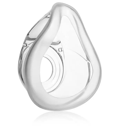
The design of an injection mold’s venting system directly impacts part quality. A well-designed venting structure can effectively prevent defects such as burning and material shortages caused by trapped air. The following examples illustrate the key points of venting design. Consider the example of venting at the parting surface of a small plastic part. A mobile phone charger housing mold uses side gate feeding. The part measures 60mm × 40mm × 20mm and is made of ABS. During initial mold trials, scorch marks appeared in the corners of the housing. Analysis revealed that this was due to air being unable to escape from the cavity corners. The solution was to create venting grooves on the parting surface near the scorched areas. The grooves were 5mm wide and 0.02mm deep, extending to the outside of the mold. After this improvement, air was successfully vented through the venting grooves, completely eliminating scorching defects. This example demonstrates that venting grooves for small plastic parts should be located at the last point of melt filling, with a depth less than the plastic’s overflow (approximately 0.03mm for ABS).
An example of combined venting for large plastic parts: a mold for a 1.8m-long automobile bumper made of PP and fiberglass. Due to the large size and complex shape of the part, a single venting method was insufficient. Therefore, a combination of parting surface venting and ejector clearance venting was adopted. Venting grooves, 10mm wide and 0.03mm deep, were created on the parting surfaces at both ends of the bumper (where the melt is finally filled). The clearances (0.02-0.03mm) between the 20 ejector pins and the mold plate holes at the bottom of the part served as auxiliary venting channels. Furthermore, a cold slug hole vent was provided at the end of the main channel to prevent cold slug from clogging the vent grooves. Mold trials showed that the combined venting system effectively expelled air and volatiles from the cavity, resulting in a fully filled part with no air-trapping defects on the surface. This example demonstrates that large plastic parts require a multi-location, multi-form venting strategy to ensure efficient venting.
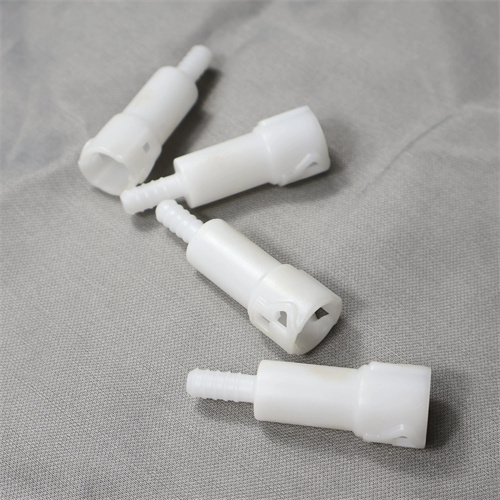
An example of using vent pins to vent deep-cavity plastic parts: A water dispenser bucket connector mold features a 35mm-deep cylindrical cavity made of PE. During mold trials, it was discovered that material shortages and bubbles frequently occurred at the bottom of the cavity. This was due to air being compressed and unable to escape when the melt filled to the bottom. The solution: A 5mm-diameter vent pin was placed at the center of the cavity bottom. The clearance between the vent pin and the mold plate was 0.015-0.02mm, and a 2mm-diameter vent hole was opened inside the vent pin to the atmosphere. When the melt filled to the bottom of the cavity, air entered the vent hole through the vent pin gap and was discharged. After this improvement, the shortages and bubbles were completely eliminated. This example demonstrates that venting of deep-cavity plastic parts should reach the deepest part of the cavity, and the vent pin clearance must be precisely controlled to prevent melt leakage.
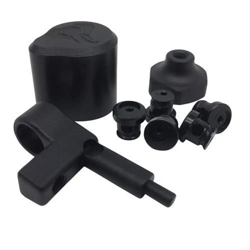
An example of combining vent grooves and exhaust wells for thin-walled plastic parts: A laptop keyboard key mold features a 0.8mm thick key, made of PC. Due to the thin walls and high melt flow resistance, underfilling is a common problem. The design solution involves installing a 3mm wide and 0.015mm deep vent groove at the end of each key cavity. A 5mm x 5mm x 3mm exhaust well is connected to the end of the vent groove. The exhaust well temporarily stores any excess melt, preventing clogging. Mold trials confirmed that this structure allows the melt to quickly fill the cavity, resulting in complete key molding without missing material. This example demonstrates that the vent groove depth should be smaller for thin-walled plastic parts, and that the inclusion of an exhaust well improves exhaust reliability.
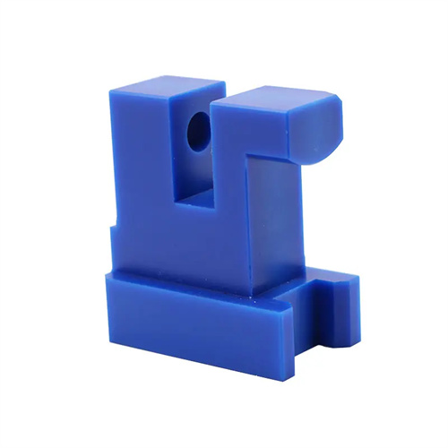
An example of venting in a side core-pulling mechanism: In a plastic pipe fitting mold with side holes, the side holes were formed by a core-pulling slider. During mold trials, air marks appeared around the side holes. Analysis revealed that the clearance between the slider and the core was too small, preventing air from venting from the side holes. Improvement measures: Two venting grooves, 2mm wide and 0.01mm deep, were created on the mating surfaces of the slider and the core, extending to the outside of the slider. At the same time, the venting grooves were ensured to be unobstructed by the mold plate during slider movement. After the improvements, the air marks around the side holes disappeared, and the surface quality of the plastic part was significantly improved. This example demonstrates that the venting of moving parts, such as side core-pulling parts, must balance exhaust function and motion stability to avoid affecting the precision of part fit due to the venting grooves.